
high voltage ac calibrator circuit

The high voltage AC calibrator circuit is designed to provide precise calibration of AC voltage outputs, which is crucial in various testing and measurement applications. The circuit architecture includes a sine wave oscillator, which is essential for generating a stable AC signal. The use of a transformer not only provides the necessary voltage gain but also ensures that the output remains stable and consistent under varying load conditions.
The LF347 quad operational amplifier plays a central role in this circuit. By utilizing two of its amplifiers for creating a negative absolute value amplifier, the circuit can effectively generate a feedback signal that is essential for maintaining amplitude stability. The feedback loop is critical for ensuring that the output voltage remains within specified limits, reducing distortion and enhancing the overall performance of the oscillator.
The LM329 reference voltage source is integral to the operation of the circuit, providing a stable reference against which the feedback signal can be compared. The gain of 100 achieved by the third LF347 is crucial for amplifying any discrepancies in the feedback loop, ensuring that the output remains accurate and reliable. The addition of the 10 µF capacitor sets the frequency response of the loop, allowing for fine-tuning of the circuit's performance.
The ability to adjust the output voltage settings using a potentiometer allows for flexibility in calibration, accommodating a wide range of output voltages without altering the frequency of the oscillation. This feature is particularly beneficial for applications requiring different voltage levels while maintaining a consistent frequency.
Furthermore, the option to incorporate the DAC1280 D/A converter enhances the circuit's functionality by enabling digital control of the output voltage. This allows for precise adjustments and the ability to store calibration settings digitally, improving the efficiency and accuracy of the calibration process. The circuit's design ensures that it can meet the demands of high voltage applications while maintaining low distortion levels, making it a valuable tool in the field of electronic calibration.This a application circuit for calibration. This circuit is called high voltage AC calibrator circuit. In another dimension in sine wave oscillator design is stable control of amplitude. This is the figure of the circuit. In this circuit, not only is the amplitude stabilized by servo control but voltage gain is included within the servo loop. A tr ansformer is used to provide voltage gain within a tightly controlled servo loop. A voltage gain of 100 is achieved by driving the secondary of the transformer and taking the output from the primary. A current sensitive negative absolute value amplifier composed of two amplifiers of an LF347 quad generates a negative rectified feedback signal.
This is compared to the LM329 DC reference at the third LF347 which amplifies the difference at a gain of 100. The 10 F feedback capacitor is used to set the frequency response of the loop. The output of this amplifier controls the amplitude of the LM3900 oscillator thereby closing the loop.
As shown the circuit oscillates at 1 kHz with under 0. 1% distortion for a 100 Vrms (285 Vp-p) output. If the summing resistors from the LM329 are replaced with a potentiometer the loop is stable for output settings ranging from 3 Vrms to 190 Vrms (542 Vp-p!) with no change in frequency. If the DAC1280 D/A converter shown in dashed lines replace the LM329 reference, the AC output voltage can be controlled by the digital code input with 3 digit calibrated accuracy.
🔗 External reference
Related Circuits
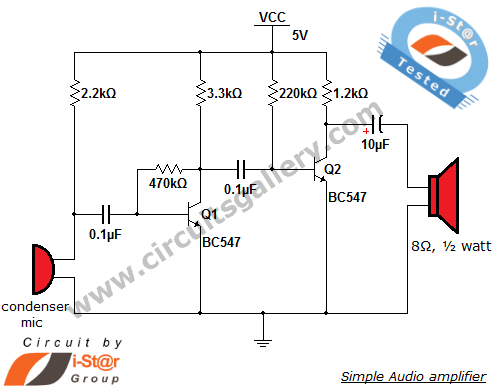
The output of the condenser microphone is coupled through a 0.1 µF coupling capacitor, which serves to eliminate DC components from the audio signal. Transistor Q1 is configured in a collector-to-base biasing mode, achieved with a 470kΩ resistor. This...
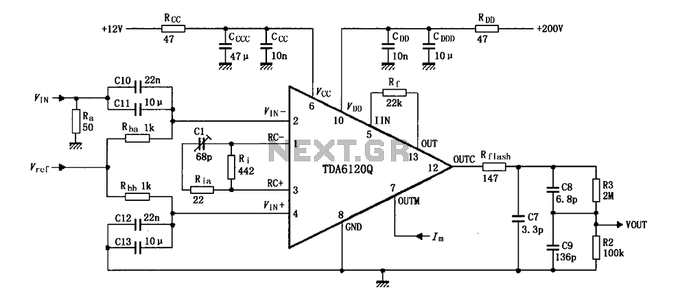
Feedback has indicated that the TDA6120Q test circuit, as shown in the figure, utilizes an input signal (Vi) composed of resistors Ra and capacitors C10 and C11, which are fed into the TDA6120Q at pins 2, 3, and 4....
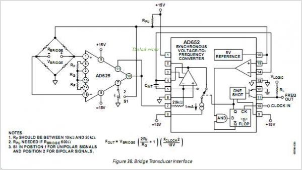
The AD654 is a monolithic voltage-to-frequency (V/F) converter that comprises an input amplifier, a precision oscillator system, and a high-current output stage. A single resistor-capacitor (RC) network is all that is needed to configure any full-scale (FS) frequency up...
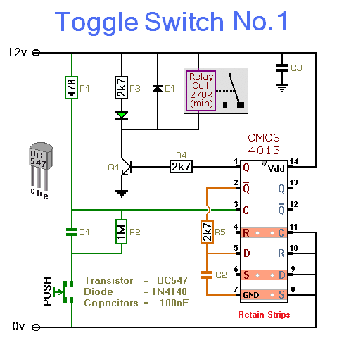
This simple circuit will energize and de-energize a relay with the push of a button. Pressing the button once will energize the relay, while pressing it a second time will de-energize the relay. The accompanying circuit provides a solid...
The IR photo transistor Q1 (Radio Shack 276-145A) or a similar component is connected to the set input (pin 6). It is essential to shield the photo transistor from direct light to ensure that the voltage at the set...
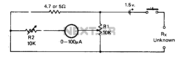
For the measurement of resistances ranging from approximately 5 ohms down to about 0.1 ohm. This circuit is highly practical. The described circuit is designed to measure low resistances with high precision, specifically in the range from 5 ohms down...