
High voltage geiger counter supply
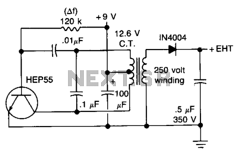
The described circuit is a high-voltage DC power supply designed to provide approximately 300 volts, which is a typical requirement for Geiger-Müller (GM) tubes used in radiation detection applications. The circuit operates at a very low current, ensuring that the power output is adequate for the GM tube's operation without risking damage to the tube or the circuit itself.
The essential components of this circuit typically include a transformer, a rectifier, and a voltage regulation stage. The transformer steps up the input voltage to a higher AC voltage level before it is converted to DC. A full-wave rectifier configuration, often utilizing diodes, is employed to convert the AC output from the transformer into DC voltage.
To ensure the output voltage remains stable at 300 volts, a voltage regulation mechanism may be implemented. This could involve using zener diodes or a series of capacitors and resistors to filter and smooth the rectified voltage. Additionally, safety features such as a fuse or circuit breaker may be included to protect against overcurrent conditions.
It is crucial to handle this circuit with care due to the high voltage output, which poses a significant risk of electric shock. Proper insulation, secure connections, and the use of protective enclosures are recommended to minimize hazards during operation. Furthermore, users should be aware of the circuit's limitations, particularly the low current output, which may restrict its use to specific applications within the field of radiation detection.This circuit will generate about 300 volts dc—at a very low current, but enough for a GM tube. be careful with the output. 🔗 External reference
Related Circuits
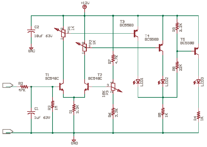
The circuit possesses significant educational value. It has not been tested. Users can simulate and test it or construct it to evaluate its performance. The circuit functions as a simple analog-to-digital converter. Optocouplers can be used in place of...
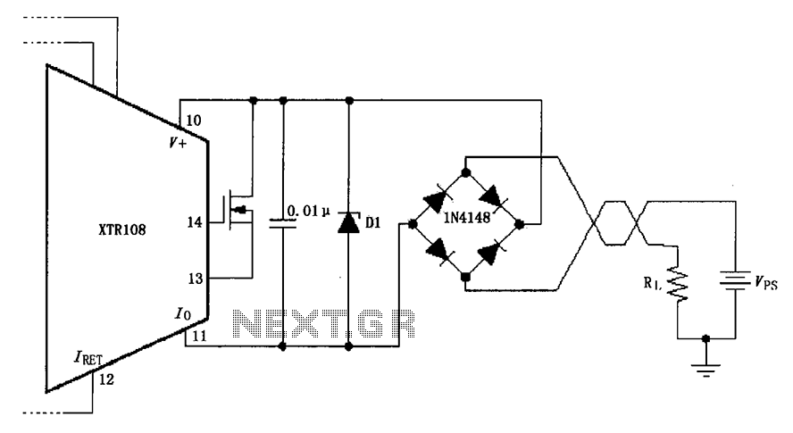
The circuit utilizes a Zener diode (D1) for overvoltage protection and a diode rectifier bridge for reverse voltage protection. The 1.4V drop across the diodes will result in a maximum voltage loss, meaning that the supply voltage (VPS) must...
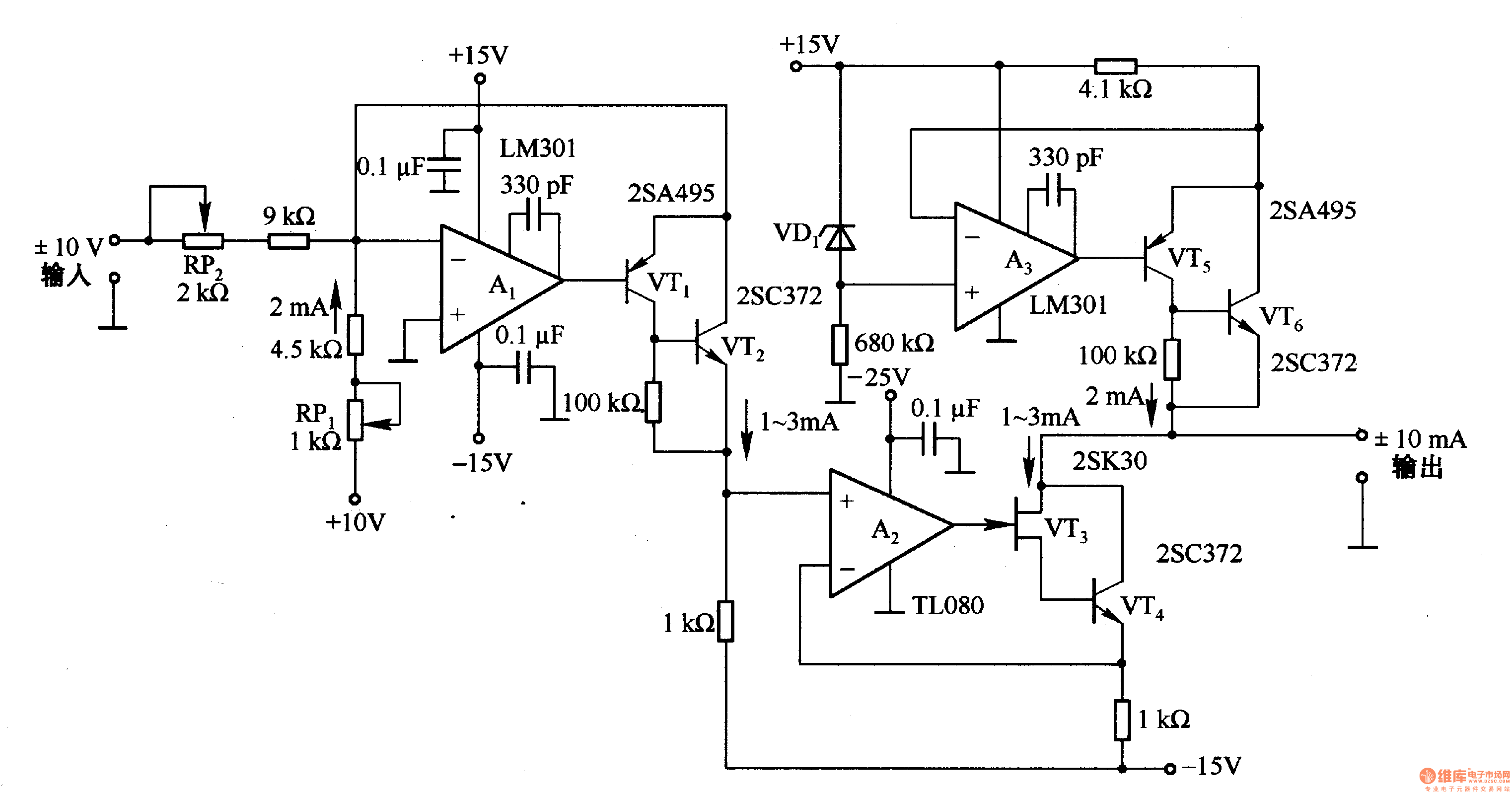
This circuit is designed for voltage-to-current conversion, specifically transforming a ±10V input voltage into a ±1mA output current. The conversion process is facilitated by operational amplifier A1 and transistors VT1 and VT2, which are responsible for altering the current...
This article describes a 2-Digit Counter using a Microchip PIC12F629. It shows what can be done with an 8-pin chip having just 5 output lines and one input line. The chip drives two 7-segment displays and this would normally...
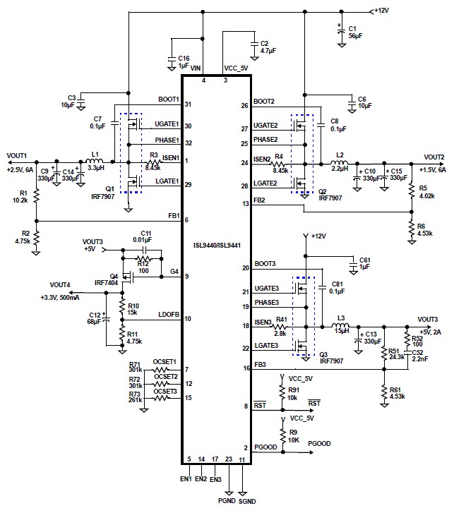
The ISL9440 quad-output synchronous buck controller IC can be utilized to design a highly efficient electronic circuit power supply that delivers four distinct fixed output voltages. The ISL9440 integrates three PWM controllers and one low dropout linear regulator controller,...
The heart of the lock is the 40022 octal counter. When first powered C2 is charged via R5 so the reset input of the counter is kept high. That causes output Q to go high while all the other...