
Basic Inverter
The inverter circuit described involves a basic configuration where the transistors Q1 and Q2 function as the primary switching elements. The choice of 2N3055 transistors is essential, as they are designed to handle significant current loads, although their limitations necessitate careful consideration of the overall power requirements. The transformer T1 plays a pivotal role in stepping up the voltage from the low-voltage side to the high-voltage output, which is crucial for inverter applications.
When rewinding the microwave transformer, the process of creating a center-tapped secondary winding is critical for achieving balanced voltage outputs. The number of turns in the secondary winding directly influences the output voltage and current characteristics, which must align with the specifications of the load the inverter is intended to drive. The use of enamel-coated magnet wire is advantageous due to its insulation properties, which allow for close winding without short circuits.
The inclusion of tantalum capacitors for C1 and C2 is a vital design consideration, as these components are capable of handling the high ripple currents associated with switching applications without the risk of failure that can occur with standard electrolytics. The specified capacitance value of 68 µF should be adhered to strictly, as deviations could impact the performance and reliability of the inverter.
In addition, the potential variability in component characteristics necessitates a methodical approach to testing and troubleshooting the circuit. Any discrepancies in transformer ratings or transistor parameters can significantly affect the inverter's functionality, thus requiring careful adjustment and possibly iterative testing to achieve the desired performance. Overall, this inverter design represents a practical solution for generating power from a low-voltage source, provided that all components are selected and implemented with precision.Q1 and Q2, as well as T1, determine how much wattage the inverter can supply. With Q1, Q2=2N3055 and T1= 15 A, the inverter can supply about 300 watts. Larger transformers and more powerful transistors can be substituted for T1, Q1 and Q2 for more power. 2. The easiest and least expensive way to get a large T1 is to re-wind an old microwave tran sformer. These transformers are rated at about 1KW and are perfect. Go to a local TV repair shop and dig through the dumpster until you get the largest microwave you can find. The bigger the microwave the bigger transformer. Remove the transformer, being careful not to touch the large high voltage capacitor that might still be charged.
If you want, you can test the transformer, but they are usually still good. Now, remove the old 2000 V secondary, being careful not to damage the primary. Leave the primary in tact. Now, wind on 12 turns of wire, twist a loop (center tap), and wind on 12 more turns. The guage of the wire will depend on how much current you plan to have the transformer supply. Enamel covered magnet wire works great for this. Now secure the windings with tape. Thats all there is to it. Remember to use high current transistors for Q1 and Q2. The 2N3055 ²s in the parts list can only handle 15 amps each. 5. You must use tantalum capacitors for C1 and C2. Regular electrolytics will overheat and explode. And yes, 68uF is the correct value. There are no substitutions. 6. This circuit can be tricky to get going. Differences in transformers, transistors, parts substitutions or anything else not on this page may cause it to not function. 🔗 External reference
Related Circuits
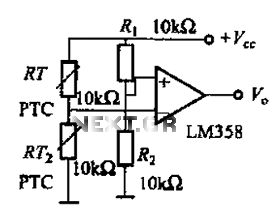
The basic application circuit for a thermistor is illustrated. Figure (a) depicts a fundamental temperature measurement circuit with limited accuracy, suitable only for applications that do not require high precision. RT represents a positive temperature coefficient thermistor; as the...
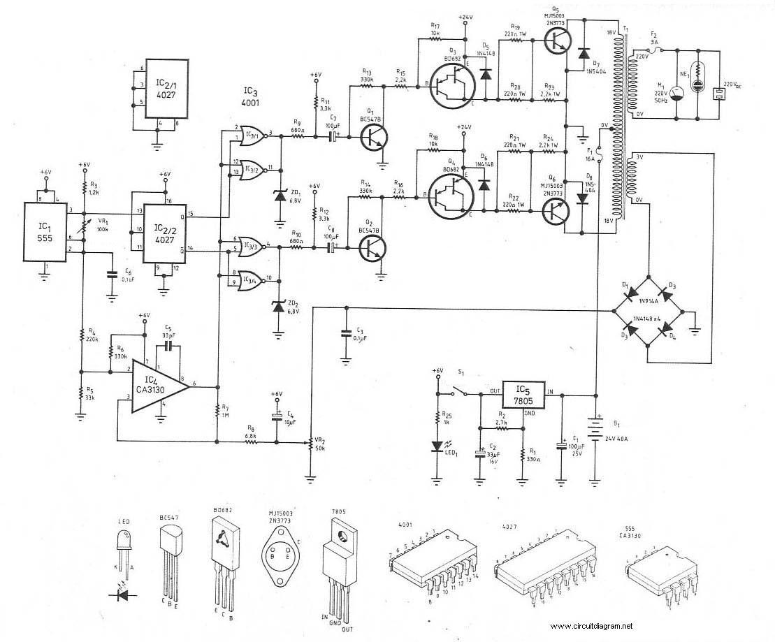
12V to 220V inverter circuit diagram, 24V inverter circuit, 24V to 220V inverter, 24VDC to 220VDC, 300W inverter, 300W inverter circuit diagram, inverter, inverter 24V to 220V, inverter circuit, inverter DC to AC, power electronics. The inverter circuits mentioned are...
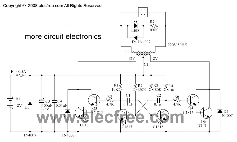
This is a small inverter rated at 30 watts. It converts DC voltage from a 12V battery to AC voltage of 220V-230V at a frequency of 50Hz, which is the same electricity used in households. It can power 2-3...
This project uses only a few of the instructions that come with PicBasic, but serves to show how easy PicBasic really is. It also shows how PicBasic strongly resembles programming the BASIC Stamp. Here we are using the serin...
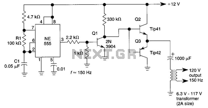
This DC-to-AC inverter utilizes the well-known 555 timer IC. A 555 oscillator circuit drives a buffer amplifier composed of transistors Q1, Q2, and Q3. The circuit operates at a frequency range of 150 to 160 Hz. Transformer T1 can...
This circuit inverter converts a 12V DC battery to 220V AC, serving as a replacement for home energy. The inverter can power small electronic devices such as lamps, radios, phone chargers, and disc players. The central component of the...