
25 Watt Power Inverter Circuit
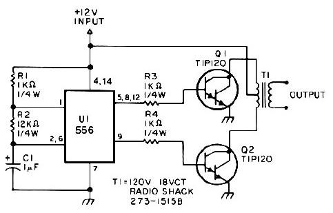
This 25-watt power inverter circuit is designed to efficiently convert low-voltage DC power into a usable AC power source. The 556 timer chip, a versatile dual timer, is employed here in an astable configuration to generate a square wave signal. The frequency of oscillation is determined by the values of resistors R2 and the capacitor C1, which together set the timing intervals for the output waveform. The output signal is taken from pin 9 of the timer chip, providing a square wave that is essential for driving the subsequent stages of the inverter.
Resistors R3 and R4 play a crucial role in maintaining the stability of the oscillator by ensuring that the output transistors, Q1 and Q2, do not interfere with the oscillator's operation. These transistors are configured in a push-pull arrangement, where one transistor conducts while the other remains off, thus alternating the flow of current through the transformer. This configuration is efficient for driving the transformer, allowing for effective voltage transformation.
The transformer in this circuit is a center-tapped unit rated for 120V / 18V. It is connected in reverse, which is a critical design choice that allows the circuit to step up the voltage from the low DC input to the higher AC output. This reversal is essential for obtaining the desired output voltage suitable for powering standard AC devices.
Overall, the inverter circuit is capable of operating over a voltage range of 4V to 16V, ensuring flexibility in input power sources. The stable output provided by the oscillator circuit is vital for maintaining consistent performance, making this inverter suitable for a variety of low-power applications, such as powering small electronic devices and appliances.This low-power 25 watt power inverter circuit which makes use of only 9 electronic parts. The inverter turns 10V to 16V DC input into 60Hz, 115V square-wave power output to operate AC electronic devices approximately 25W. The very first section of the 556 timer chip is wired as an astable oscillator with R2 and C1 setting the frequency.
The output is presented at pin 9. Resistor R3 and R4 maintain output transistors Q1 and Q2 from loading down the oscillator. The two transistors drive the transformer push-pull fashion. When one transistor is biased-on, the other is cut-off. The transformer is a 120V / 18V CT unit which is connected backward, so that is steps the voltage up rather than down. Oscillator circuit U1, R1, R2 and C1 operates from about 4 to 16V with a really stable output. 🔗 External reference
Related Circuits
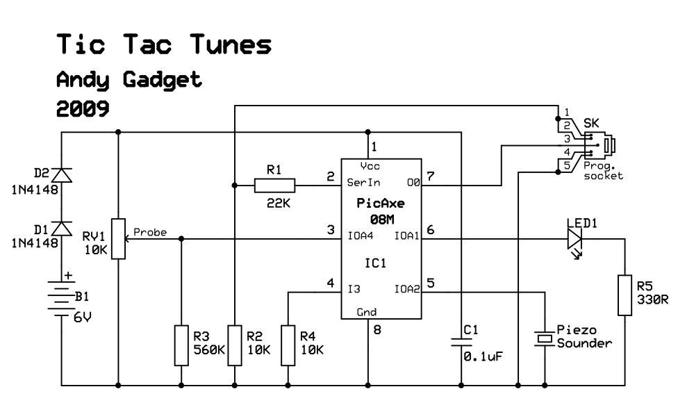
Due to limited space, a small 6V battery is utilized, and the voltage is reduced by 1.2V to 4.8V using diodes D1 and D2. The PicAxe chip is employed in the circuit. In this circuit design, the primary power source...
The core of the circuit is a two-transistor flasher with frequency modulation applied to the base of the first transistor. When the pushbutton is pressed, the oscillation frequency increases to a peak, and upon release, the frequency decreases due...
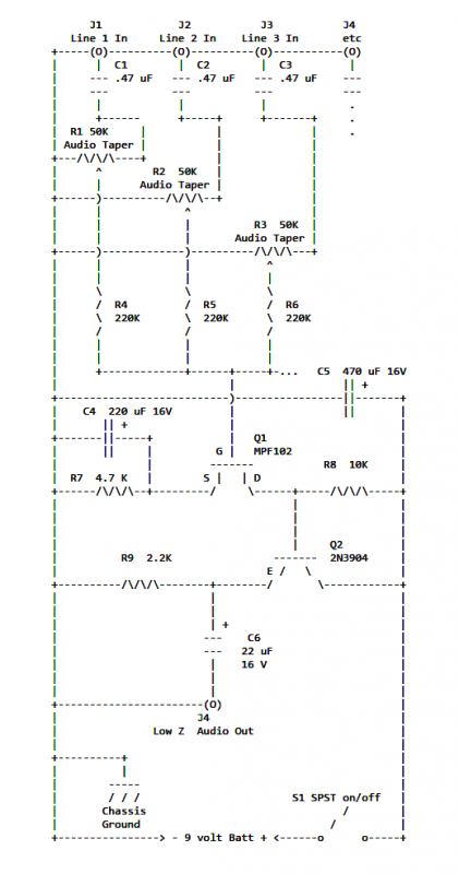
If two of these circuits are made in the same enclosure for stereo, then there can be a single power supply to run both of them. There should be a resistor in series with the incoming 9V+ lead so...
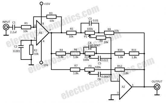
This three-band equalizer circuit functions as an active filter network for bass, mid, and high audio frequencies. It is built around the LM833 operational amplifier from National Semiconductors. The output of this three-way graphic equalizer is configured to be...
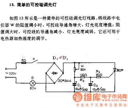
A simple silicon-controlled rectifier (SCR) dimmer circuit is depicted in Figure 13. This circuit is designed to control the brightness of lights. As the resistance in the potentiometer decreases, the conduction angle of the SCR increases, resulting in an...
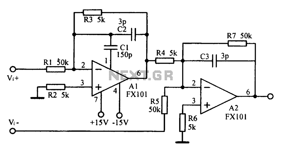
Common mode input voltage up to a difference of 100V enlarged circuit diagram. The circuit diagram described features a design capable of handling a common mode input voltage with a differential range of up to 100V. Such a configuration is...
Warning: include(partials/cookie-banner.php): Failed to open stream: Permission denied in /var/www/html/nextgr/view-circuit.php on line 713
Warning: include(): Failed opening 'partials/cookie-banner.php' for inclusion (include_path='.:/usr/share/php') in /var/www/html/nextgr/view-circuit.php on line 713