
HIGH VOLTAGE NEGATIVE ION GENERATOR
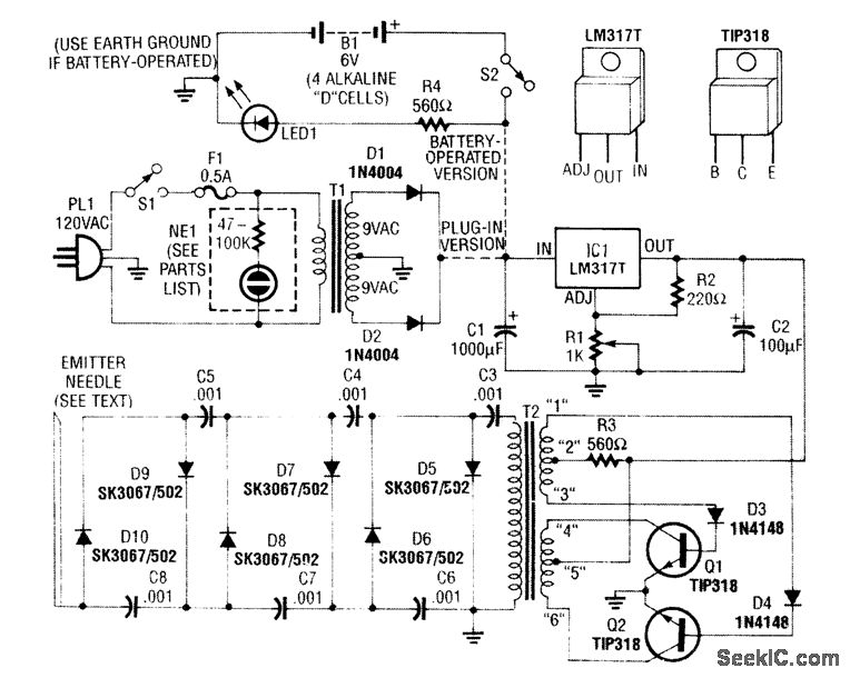
The circuit employs a modified flyback transformer, which is known for its ability to generate high voltages efficiently. The flyback transformer operates by storing energy in its magnetic field during the flyback period of the horizontal scan in a television set. In this application, it is adapted to produce a higher output voltage than typical television applications.
The voltage multiplier is a crucial component in this circuit, as it steps up the voltage produced by the flyback transformer. This is typically achieved through a series of capacitors and diodes arranged in a configuration that allows for the accumulation of voltage. The diodes prevent backflow of current, while the capacitors store charge, effectively multiplying the voltage output.
The output voltage, which can vary between 9 kV and 14 kV, is then directed to a discharge needle. This needle serves as an ion emitter, where the high voltage creates a strong electric field that ionizes the surrounding air, resulting in the production of negative ions. These ions can have various applications, such as improving air quality or in certain industrial processes.
The design of the circuit must ensure that all components can handle the high voltages involved, particularly the voltage multiplier and the discharge needle. Proper insulation and safety measures should be implemented to prevent electrical hazards. Additionally, the circuit may require a suitable power supply to energize the flyback transformer, which must be capable of providing the necessary input voltage and current for stable operation.
Overall, this circuit exemplifies the use of high-voltage technology in generating negative ions, leveraging the principles of electromagnetic induction and voltage multiplication effectively.A modified B/W TV flyback transformer is used in this circuit with a voltage multiplier to produce 9- to 14-kV negative voltage. This is connected to a discharge needle to produce negative ions. 🔗 External reference
Related Circuits
This is a voltage multiplier circuit. The first circuit is used to double a square wave (of any amplitude). However, there is a drawback of approximately 2V losses in the base-emitter. A voltage multiplier circuit is designed to increase the...
8051SBC USB and GLCD Expansion Board, electronic circuit schematic wiring diagram for the 8051SBC USB and GLCD Expansion Board. The 8051SBC USB and GLCD Expansion Board is designed to enhance the functionality of the 8051 microcontroller system by providing additional...
The circuit below is designed to be used with the bi-directional lamp sequencer shown above on this same page. Two additional transistors are used to increase the current from the 74HCT138 decoder to control 12 volt 25 watt lamps....

In this circuit, IC1 (CD4009) is utilized as a square-wave oscillator operating at approximately 25 kHz. Capacitor C1 and resistor R1 determine this frequency. Capacitors C2, diode D1, diode D2, and capacitor C3 create a peak-to-peak rectifier, which produces...
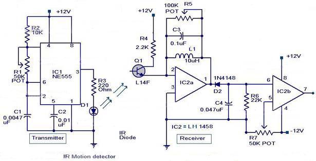
The following circuit illustrates an Infrared Motion Sensor circuit diagram. Features include the use of the NE555 integrated circuit, with a detection zone coverage of 80 degrees. The Infrared Motion Sensor circuit utilizes the NE555 timer IC configured in a...
The output F1 pin 17 of the PLA U17 goes low when the BASIC ROM is selected. The KERNAL ROM resides at locations $E000 - $FFFF. The output F2 pin 16 of the PLA U17 goes low when the...