
Current Sensing for High Voltage Application
The LTC6101 is a precision current sense amplifier designed to operate in high voltage environments, making it suitable for applications where accurate current measurement is crucial. This device features a wide common-mode voltage range, allowing it to accurately sense current in high-side applications without being affected by the high voltage levels present in the circuit.
The basic configuration of the current sensing circuit involves placing a shunt resistor in series with the load. The voltage drop across this resistor, which is proportional to the current flowing through it, is then amplified by the LTC6101. The gain of the amplifier can be set using external resistors, enabling flexibility in the design to accommodate various current ranges.
The circuit typically includes the following components:
1. **Shunt Resistor (Rs)**: This low-ohmic resistor is placed in series with the load. The value of the shunt resistor is chosen based on the maximum current expected and the acceptable voltage drop across it.
2. **LTC6101**: The operational amplifier is configured to amplify the voltage across the shunt resistor. It has a high input impedance to minimize the impact on the current being measured.
3. **Feedback Resistors (Rf and Ri)**: These resistors set the gain of the LTC6101. The gain can be calculated using the formula: Gain = Rf / Ri. Selecting appropriate resistor values allows for customization based on the specific application requirements.
4. **Power Supply**: The LTC6101 requires a dual power supply to operate effectively in high voltage scenarios. The supply voltages must be chosen to ensure that the amplifier operates within its specified limits while providing sufficient headroom for the input signal.
5. **Output Filtering**: Depending on the application, it may be necessary to include capacitors at the output to filter any high-frequency noise, ensuring that the current measurement is stable and accurate.
The output of the LTC6101 can be connected to an analog-to-digital converter (ADC) for digital processing or directly to a microcontroller for real-time monitoring and control. This setup allows for enhanced functionality, such as overcurrent protection, load monitoring, and system diagnostics.
In conclusion, the LTC6101-based current sensing circuit is a robust solution for high voltage applications, providing accurate and reliable current measurements essential for various industrial and consumer electronics applications.High voltage current sensing/monitoring can be designed using LTC6101 op-amp. The following current sensing circuit is capable of measuring electrical current. 🔗 External reference
Related Circuits
Commonly used 3-pin linear voltage regulators, such as the LM317, cannot handle input voltages exceeding approximately 30V. The LR8A from Supertex Inc is a new adjustable three-pin regulator capable of accepting input voltages up to 450V and supplying an...
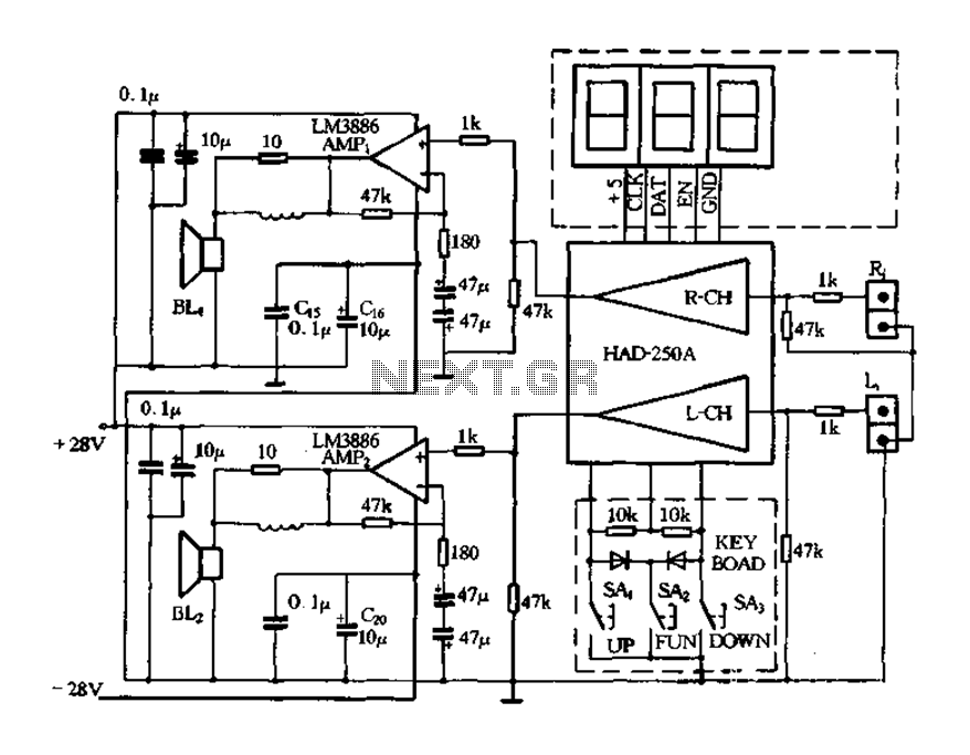
Figure 4-20 illustrates the HAD250A-3 active speakers and amplifier circuit, which features the LM3886 integrated amplifier. This circuit operates with a 25V power supply and delivers an output power of up to 50W per channel, making it suitable for...
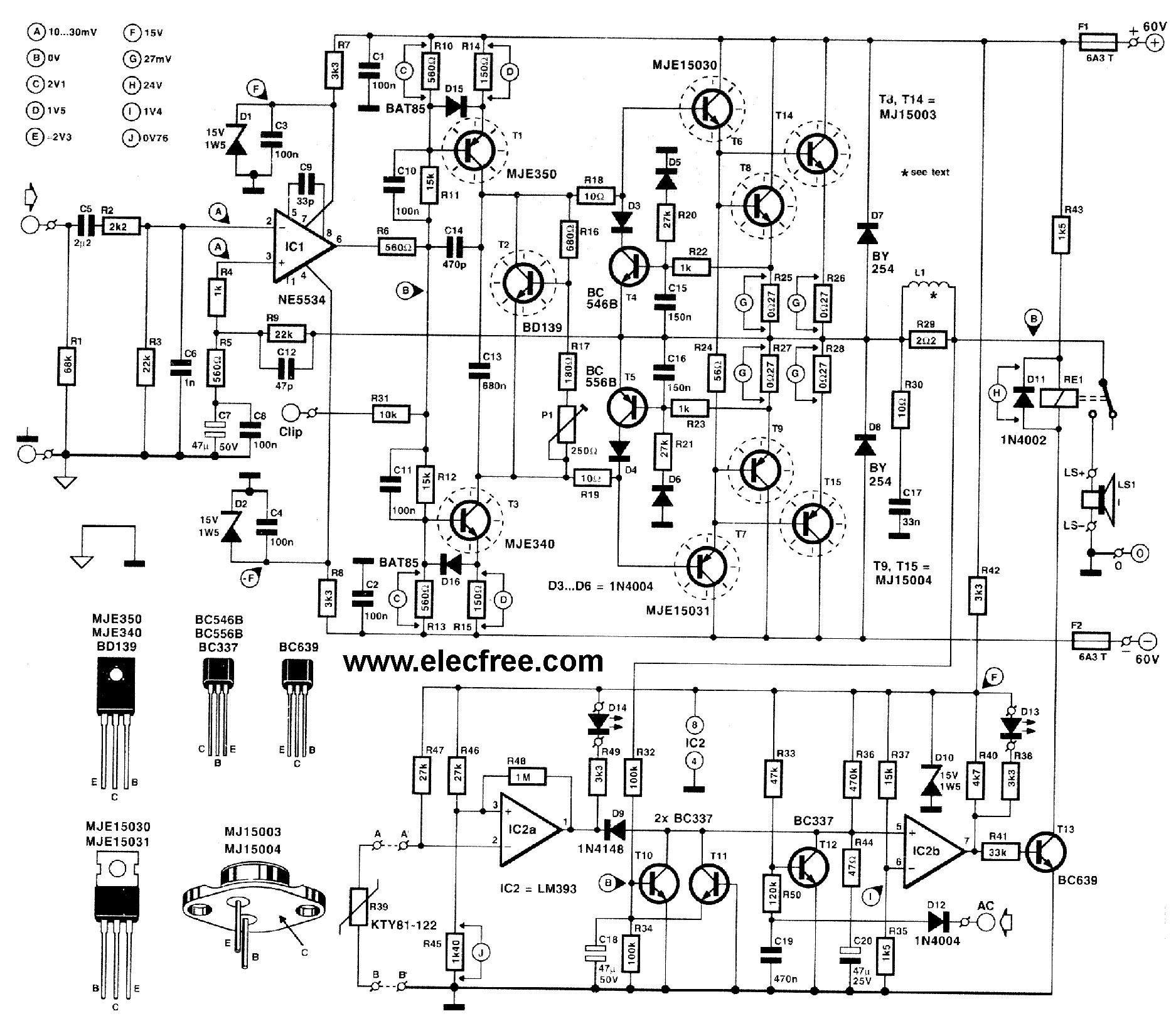
This circuit is designed for friends who are interested in high-power amplifier circuits. It can deliver approximately 300 Watts RMS and operates as an OCL (Output Capacitor-Less) Class AB amplifier, providing high sound power while systematically protecting the loudspeaker...
This circuit addresses the challenge of transmitting data over a cable that lacks available conductors. The data is modulated using On-Off Keying (OOK) and superimposed on a high-frequency carrier, allowing it to be transmitted over a low-voltage power supply...
The receiver is a triple superheterodyne receiver with two phase-locked loop (PLL) guided local oscillators. The first local oscillator (LO) operates at 2.1 GHz and can be adjusted in increments of 500 kHz, down-converting the received signal to a...
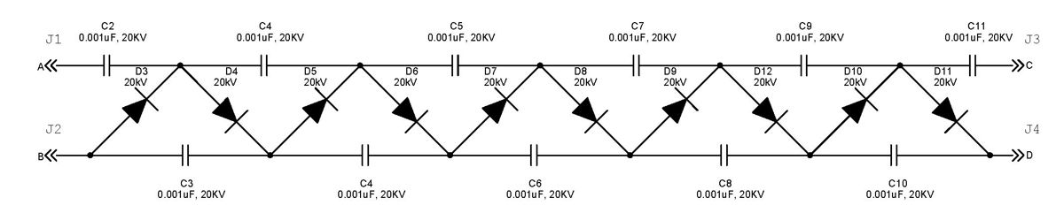
The Cockcroft-Walton multiplier employs a series of diodes and capacitors arranged in a cascade to generate a high-voltage DC potential from an AC input. This circuit topology utilizes diodes to charge capacitors in parallel and discharge them in series....