
Speech Circuit Controlling the Robot
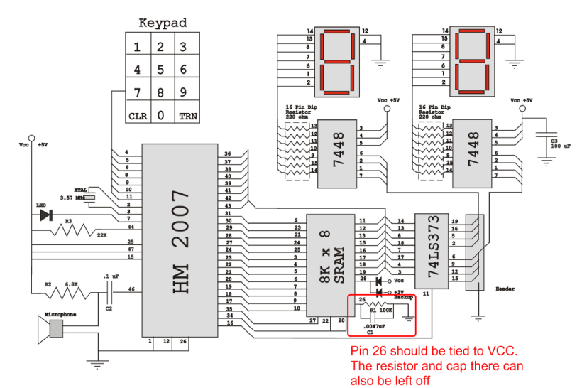
The circuit design involves several critical components, including the RAM chip, HM2007, and address and data lines. The RAM chip's pin configuration is essential for ensuring proper functionality, particularly regarding the enable signal. In this case, the enable signal's inversion must be correctly interpreted in the schematic to avoid operational failures.
When designing the schematic, it is crucial to maintain the integrity of the address and data lines. The alignment of SA0-A0 and D0-D0 must be consistent across both the HM2007 and the RAM chip to ensure seamless communication between them. This alignment facilitates the flow of data and control signals, which is vital for the circuit's operation.
For the schematic layout, it is recommended to use a software tool that allows for precise placement of components and wiring. The schematic should clearly represent the connections between the HM2007 and the RAM chip, including all necessary power and ground connections.
In the event that circuit issues persist, a systematic troubleshooting approach should be adopted. This includes verifying all connections, checking for shorts or opens in the circuit, and testing the functionality of individual components. If the components are suspected to be defective, replacement chips should be procured from a reliable supplier to ensure project continuity.
Overall, attention to detail in the schematic design, thorough testing, and proper component selection will significantly enhance the likelihood of successful project completion.Triple check your pins on the datasheets for your chips and make changes if you need to. In my case, The RAM chip I used had a non-inverted enable on pin26, but the schematic assumed the enable was inverted. This caused the circuit not to work until I figured it out. Also, feel free to move the address lines around. These lines are mixed up on the schematic only to facilitate the PCB designed from Images co. Aligning SA0-A0 from the HM2007 to RAM and D0-D0 in the same fashion caused no problems for me. It works great and is easier to build on a breadboard. Soln. I am sorry that I cannot help in these cases at all as I did not choose to use this mode on the chip. However, there is some information in the Images Co datasheet Addendum and some more info on the talking toaster page as well as some info for interfacing the Arduino.
(< that last link is the HM2007 wiki, great resource. ) 4. ) Redo the schematic from scratch (not as hard as you might think!) Use address lines SA0-A0 and data lines D0-D0 like in this schematic. Draw your own schematic. You may need to enlist the help of a professor or teacher to help you with this. 5. ) If nothing you do is fixing your project, it is very likely that your RAM chip or HM2007 is bad. This is not the most likely problem, however, I did encounter a bad HM2007 chip and a bad RAM chip. The best bet here is to order new chips. I made several orders from Images Co and was charges overall about $60 for shipping on everything. 🔗 External reference
Related Circuits

This circuit needs a Faraday shield, which is connected to 0V. To make this one wrap a tin foil around the coil and connect to 0V. Then you can use this circuit to find metal. Tune your mw radio...

This document outlines a straightforward circuit diagram for a musical horn utilizing two NE555 integrated circuits (ICs). Both ICs are configured as astable multivibrators. The output from the first multivibrator is connected to the discharge pin (pin 7) of...

An obstacle-avoiding robot is an intelligent device that can automatically sense and navigate around obstacles in its path. It is designed without a microcontroller to simplify the circuitry and programming requirements. Understanding the circuit diagram is essential for constructing...
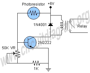
This is a light sensor circuit designed to detect light and activate a relay. The circuit is straightforward and requires only a few components. The operation of the circuit is simple: when the photoresistor detects light, it will turn...
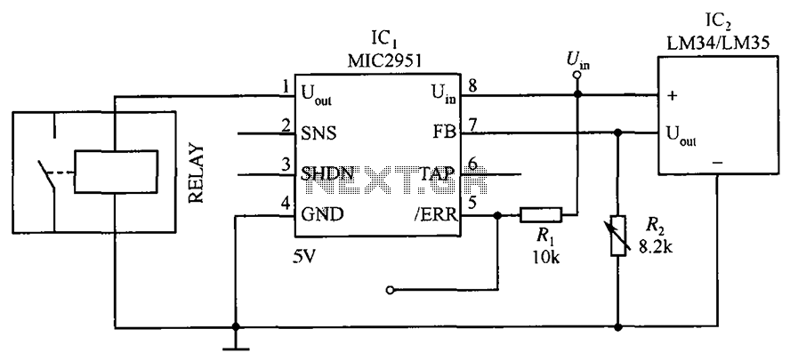
The circuit depicted in the figure utilizes a thermal protection system featuring the MIC2951 component. The temperature threshold can be adjusted by modifying resistor R2. The thermal protection circuit employing the MIC2951 is designed to monitor and regulate temperature within...
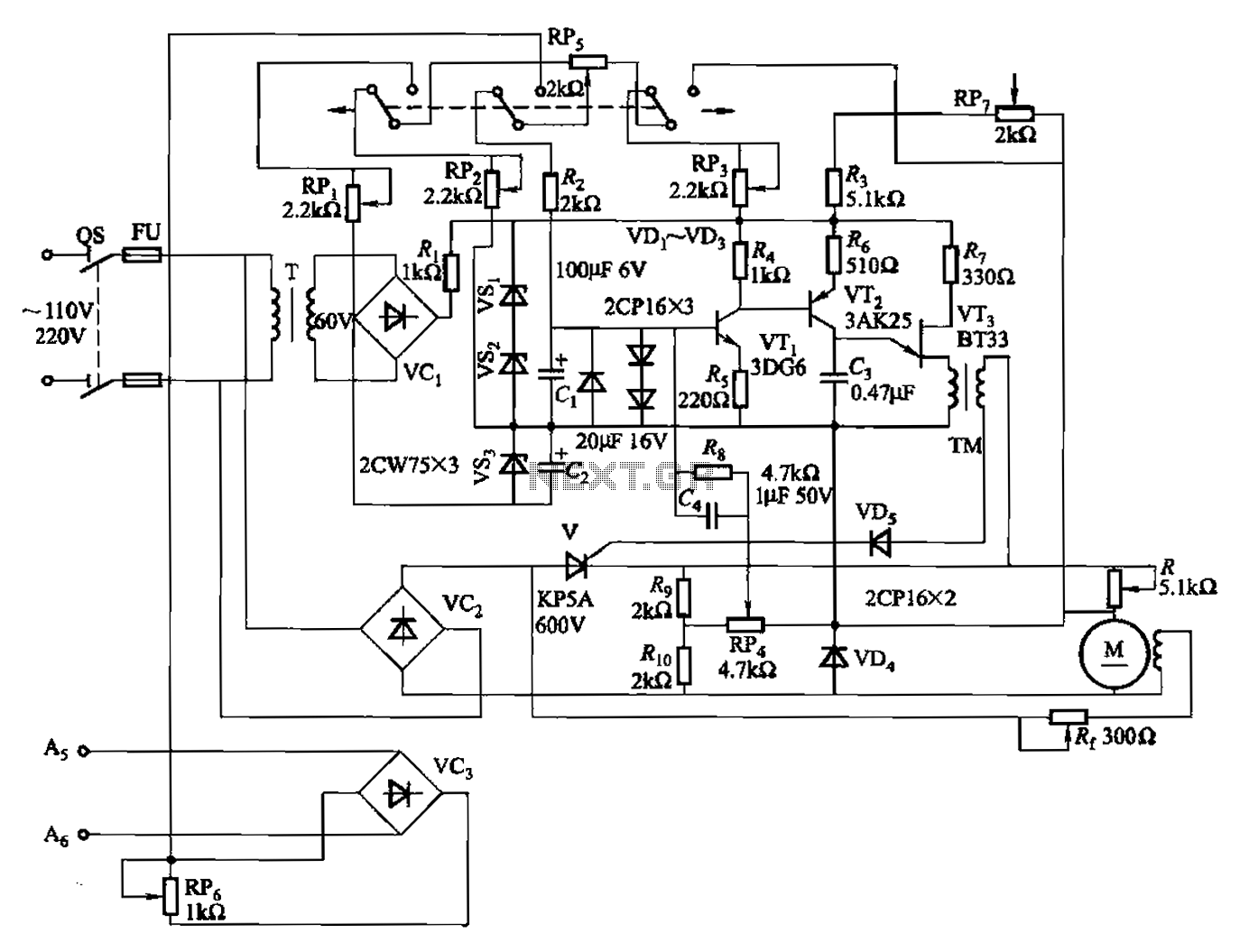
A 100W full-wave single-junction transistor trigger control circuit designed for constant or variable speed control of a wire feed motor. The input control signal consists of a voltage adjusted by the master potentiometer (RPs) and a feedback voltage from...