
Home Electrical Wiring

The described electrical configuration demonstrates a fundamental understanding of residential power distribution systems. The utilization of a split-phase system allows for efficient power delivery while accommodating a variety of household appliances. The implementation of GFCI and AFCI protections reflects adherence to safety standards outlined by the NEC®, ensuring that areas prone to moisture or potential electrical faults are adequately safeguarded. The choice of receptacles, such as the NEMA 5-15R and high-current options, illustrates the need for flexibility in accommodating different load requirements. Additionally, the emphasis on balancing loads across the two lines is crucial for maintaining system stability and preventing overload conditions. The design considerations outlined in this description provide a comprehensive overview of the operational principles and safety measures integral to residential electrical systems.Whether you are considering a backup power system, want to add another electric circuit, or are going to install a new appliance, it is important to understand the home`s electrical wiring basics and applicable codes. First, let`s briefly review how electricity gets to your house. Most residential and light commercial homesin U. S. have a single-phase 3-wire 120V/240V service. Itconsists oftwoinverted relative to each otherlines and a grounded neutral. Connecting an electric load betweenany line and the neutral yields 120 volts AC. Connecting between both lines yields 240 volts AC (see the diagram). The two 120V buses are derived from a step-down distribution transformer, which isusually mounted on a pole. Its secondary winding has a grounded center tap connected to neutral wire. The two endterminals are electrically hot with respect to the neutral. Note that both lines are derived from the same utilityphase. That`s why such configuration is often called split phase. The threeconductors go from the pole toyour electric meter. From the meter they run to the panel containing the main service disconnect. From there thelines go to magnetic circuit breakersthat protectindividual branches. The branch breakers can be mounted in a separate distribution panel or can be incorporated into the main panel.
The individual outlets in the homes are normally NEMA 5-15R duplex. The National Electric Code (NEC ®) 2014 specifies ten locations in dwelling units where the outlets should have GFCI (article 210. 8). Particularly, GFCI should be in bathrooms, garages, kitchens, etc. The article 210. 12 additionally requires special arc-fault circuit interrupters (AFCI) for most types of rooms. Of course, if you don`t touch it you are not required to upgrade, but if you modify, replace, or extend any branch-circuit, you are supposed to add an AFCI either at the beginning of that branch or at its first outlet.
Why, you may ask, do we need a 3-wire configuration Would not a single 120Vbus be enough The case is, a standard wall outlet NEMA 5-15R is rated to 15A. Hence, the maximum power you can draw fromsuch an outletis 15G—120=1800 volt-amps. Moreover, for continuous loads, NEC ® recommends to limits the current on receptacles to 80%. Therefore, steady statecurrent should be less than 12A (which corresponds to 120G—12=1440 VA). What if your applianceconsumes more power There are of course high-currentreceptacles, such as twist-lock125 Volt 30 Amp NEMA L5-30R.
However, large appliances such as a central a/c ordriers are usually designed to work from 240V. This is done in order to reduce energy losses in the cables. Remember, power is volts times amps. When you double the voltage, you need half the current to deliver the same wattage. And for lower currents you can use lower conductor thickness. That`s the main reasonwe are getting 240V. As you can see from this wiring diagram, it is obtained from two 120VAC lines, so we have two voltage levels. Of course, in theory, if mostsmall residentialappliances were not designed for 120V, we could do away with it and use a more efficient 240V or any other higher voltage system.
As we know, Europe and most other countriesemploy a 2-wire 220-240V wiring. Historically, U. S. initially adapted a lower potential level mainly because the original Edison`s electric bulbs were optimized for110V. Later on, it was raisedto 120V. Note thatthe total electric current consumed by your home is split between twolines and you should try to balanceyour loads.
Note that thereceptacle`s rating is not the only factor that limits the amount of current you can draw from it. Often, each breaker servesseveral outlets. The allowableamperage is therefore also limited by the rating of the breakers and the size of the wires.
Continuous electric load on eachcircuit should not exceed 80% of the breaker ratings per Table 210. 21(B)(2) of NFPA70 ®. The branch conductors should be rat 🔗 External reference
Related Circuits
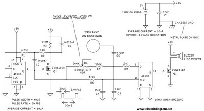
This is a door knob touch alarm designed for home security purposes. The alarm will activate when someone touches the metal door knob. This circuit will not function on a fully metal door. Currently, circular batteries are used, but...
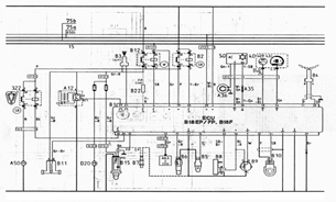
The following document contains information related to the electrical installation schematic diagram for the Volvo 440. It includes the wiring schematic for the Volvo 440, 460, and 480 series. The Volvo 440, 460, and 480 series vehicles feature a comprehensive...
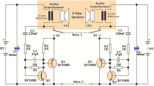
Wiring 2-Wire Intercom. According to Wikipedia, an intercom is a stand-alone electronic communications system intended for limited or private dialogue. A 2-wire intercom system is designed to facilitate communication over a limited distance, typically within buildings or residential areas. The...
Electrical lines that include lighting circuits originate from the main distribution panel of the installation. Each line consists of three conductors: phase, neutral, and ground. All three conductors extend to the terminal point of each luminaire, and if the...
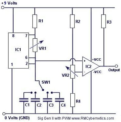
Construct a signal generator using readily available components. It should produce a square wave with variable frequency and adjustable pulse width. This device can be utilized for various applications, including DC motor speed regulation, dimming of lamps or LEDs,...
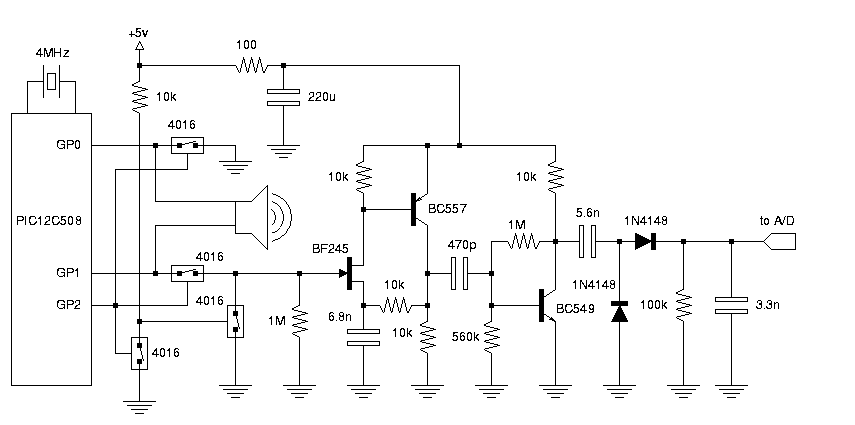
This is the electronic schematic of a homebuilt SONAR system. It utilizes a single piezoelectric transducer for both transmission and reception, which is switched from transmit (TX) to receive (RX) mode using four 4016 analog switches. A high-gain amplifier...