
Homebrew Utrasonic Imager

The SONAR system's schematic design is centered around the integration of a piezoelectric transducer, which serves dual purposes of emitting and receiving ultrasonic waves. The switching mechanism is facilitated by four 4016 analog switches, which are controlled by the microcontroller to alternate between TX and RX modes. The high-gain amplifier stage is essential for enhancing the weak echoes received from the environment, ensuring that even faint signals can be processed effectively. The rectifier stage then converts these amplified signals into usable voltage pulses that represent the time delay of the echoes, which correlates to the distance of obstacles in the environment.
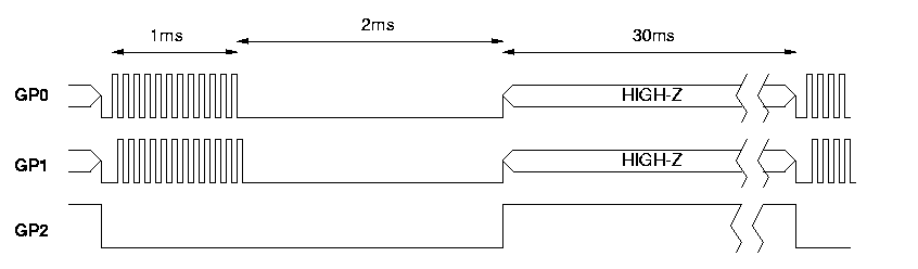
The PIC12C508 microcontroller is pivotal in managing the timing and control logic of the SONAR system. It orchestrates the sampling of echoes at a rate of approximately 18 kHz, ensuring that the data captured is both timely and accurate. The 8-bit resolution allows for a range of echo amplitudes to be quantified, although this resolution may impose limitations on the precision of distance measurements.
The system's operational range is notably limited by the initial decay caused by the transducer's residual oscillation, which restricts effective detection to distances greater than 50 cm. The identification of echoes, such as the prominent peak at sample 230, illustrates the system's capacity to detect and measure distances to objects, like walls, at a known distance of 2.5 meters.
Mechanical scanning of the SONAR system is achieved through a stepper motor, which allows for a systematic exploration of the surrounding environment. This capability is enhanced by the use of a paper horn, which focuses the ultrasonic beam and minimizes divergence. However, this focusing also introduces complications, such as the reflection of ultrasonic power back towards the transducer, which can produce misleading back echoes, especially at shorter ranges.
In summary, the SONAR system is a sophisticated integration of various electronic components that work together to provide effective distance measurement capabilities. Its design considerations, including the trade-offs between beam divergence and echo clarity, underscore the complexities involved in developing reliable ultrasonic sensing systems.This is the electronic schematic of the homebuilt SONAR. Only one piezoelectric tranducer is used for both tramsmit & receive. This transducer is switched from TX to RX via the four 4016 switches. A high gain amplifier stage & rectifier translates the received echoes into voltage pulses. The timing is controlled by the PIC12C508 8-pin microcontrol ler as it is shown in the following figure: The SONAR system is connected to an analog input of a 68HC11 prototype board. The echos are sampled at about 18KHz, with 8 bit resolution. The captured data looks like this: The starting decay is due to the residual trasducer oscilation. This decay limits the minimun range of the SONAR to about 50 cm. The peak around sample 230 is due to a wall echo. The wall was located 2. 5m away from the SONAR. The next graph shows the echo of a close obstacle (me :) Two sucessive scans are shown: Then, the SONAR was mechanically scanned with the help of an stepper motor controlled by the 68HC11.
The transmited beam was also focused through a paper horn. The results were: With the use of this lens the beam divergence was greatly reduced, but another problem arises: a notable fraction of the ultrasonic power is reflected back, causing undesired echoes that can be misinterpreted in the short range. The following graph shows the results obtained with the lens. The close echoes in the left are in fact back echoes. In the other hand, the distant echoes are a lot better resolved. 🔗 External reference
Related Circuits
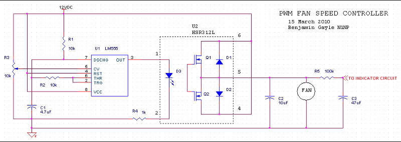
A fan speed controller for computer fans consists of two sections: one for manual speed control and another for automatic temperature-dependent speed control. Additionally, there is a section for a simple LED output indicator. While it is common to...
This time, we will share information about Yo3dac's homebrew RF circuit design ideas, including the latest updates from Onmilwiki. Yo3dac is known for innovative approaches in the realm of radio frequency (RF) circuit design, particularly within the homebrew community. The...
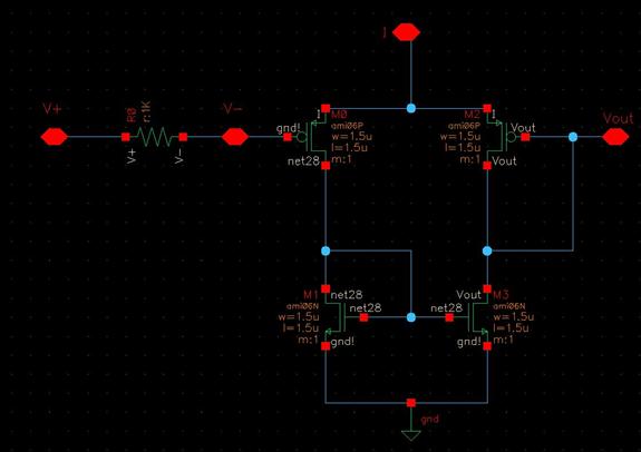
The objective of the project is to design an imager chip for laser-scanned 3-D depth/range finding. The project is divided into two modules: Pixel Array/Centroid Detection and Analog-to-Digital Conversion (ADC). The pixel array/centroid detector tracks the centroid of the...
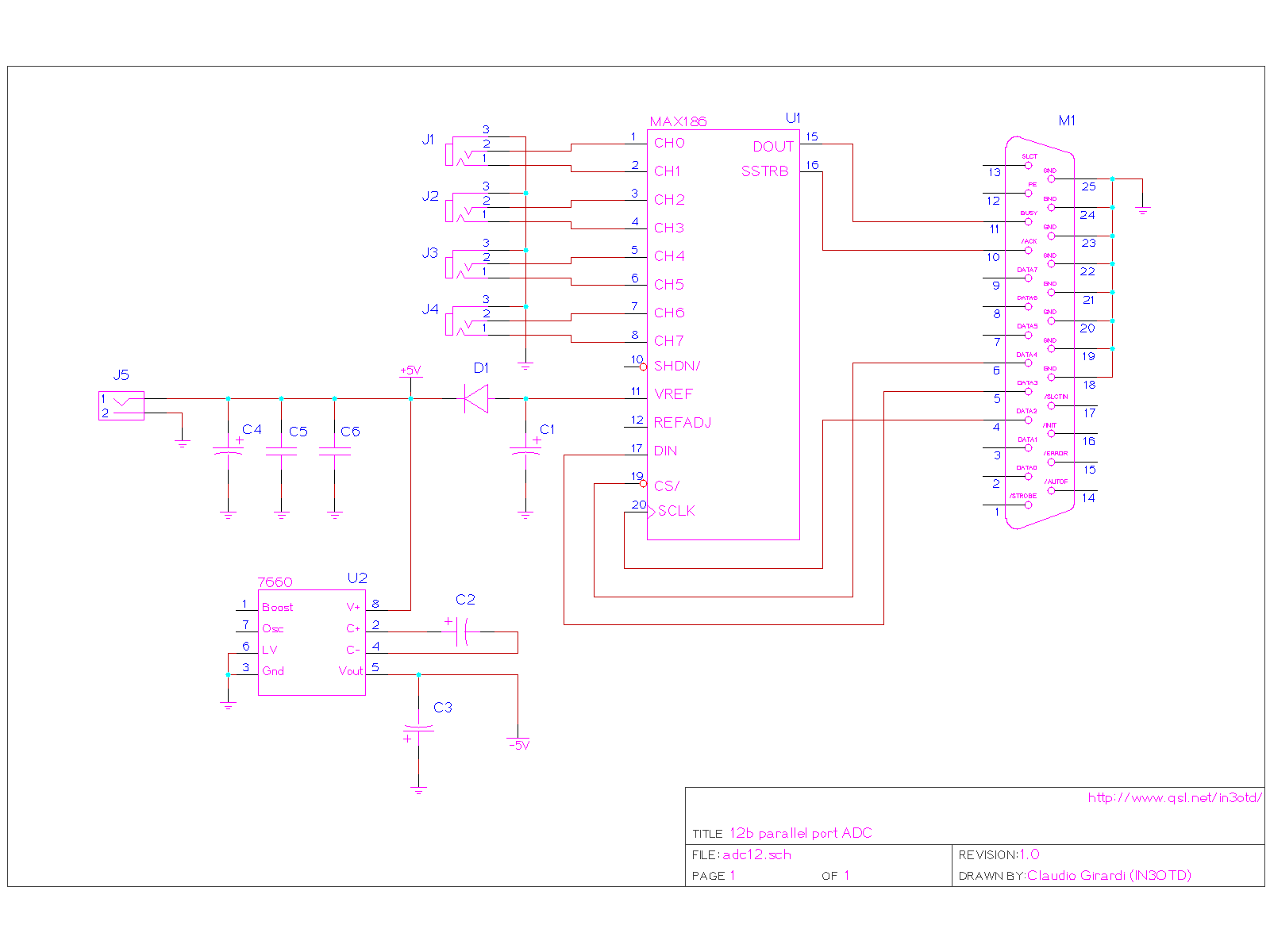
This simple PC parallel port ADC features 12-bit resolution and four differential input channels. The chip, MAX186, can achieve speeds up to 133 k samples per second, although the actual performance will depend on the software utilized. A basic...
This section will list several projects that enable the construction of RF design test equipment. Some projects will require microwave construction techniques and basic electronic skills, but the tools created will be comparable to those used by professionals. The...
The electronic schematic of the homebuilt SONAR utilizes a single piezoelectric transducer for both transmission and reception. This transducer is switched from transmission (TX) to reception (RX) using four 4016 switches. A high-gain amplifier stage and rectifier convert the...