
all about wiring diagram

The circuit described serves as a versatile platform for various applications, including DIY projects and home lighting solutions. Its design caters to individuals who appreciate originality and seek to create unique lighting atmospheres. The circuit's capability to harness solar energy to power LED lights adds an innovative dimension to traditional lighting methods. The integration of 12V LED lights enhances its functionality, allowing creative expression while maintaining an elegant aesthetic.
Amplifiers operating from a 12V DC supply typically deliver limited power and are not usually of high fidelity. However, a compact stereo amplifier designed for a 14.4V supply can output 20 watts per channel into 4-ohm loads with low distortion levels. This makes it suitable for various applications, including use in vehicles or portable setups where 12V DC is available. The amplifier design emphasizes simplicity, making it accessible for beginners and ideal for projects that do not require complex AC power supplies. The use of a TDA7377 power amplifier IC ensures improved performance, with a total harmonic distortion (THD) significantly lower than previous designs. The amplifier's self-protection circuitry enhances its durability, allowing it to operate reliably under various conditions.
In addition, a motorcycle alarm circuit can be constructed with minimal components, utilizing two transistors to drive a relay that activates a buzzer. The design allows for various normally-open switches, including mercury switches for detecting movement. Adjustments can be made to the timing of the alarm based on the characteristics of the components used. The circuit board requires protection from moisture to prevent malfunctions. A 1-amp in-line fuse is essential for safeguarding the wiring, not the circuit board itself. The alarm can be configured to activate automatically when the ignition is turned off, ensuring it remains functional in various scenarios. This low-power standby design makes it suitable for applications beyond motorcycles, such as securing personal belongings against theft.This is door knob touch alarm for your home security purpose. The alarm will be activated when someone touch the metal door knod. This circuit won`t work on full metal door. Now we use the batteries are circular, here the designers propose a new concept to design six-sided shape for battery, place the whole up and that is cellular, and compared to the gap of the round, its unique modeling can save a lot of packaging and shelf space, and because it is angular, it is not as round as we do not know where to roll when placing it on the desktop. Perhaps few people know Philippe Starck, but he is a wizard designer from Paris, even more he was known for his devils architect, his work almost cover everything about modern life.
His brilliant ideas and refined let the world wonder and be incredible again and again from the Microsoft design style different mouse to the new company produced the LED lamp design embodies a wide range of cooperation, the main lighting design by French designer Philippe Starck completed the text on the poles by the American artist Jenny Holzer design, electronic components from the accountant Moritz Waldemeyer, crystal material is from the King of Baccarat crystal brands, and finally by the complete Flos lamp manufacturing. Hooo! Is a limited edition of the lamp, the lamp is so rare appearance of fashion, highlights a tall, low-key luxury and taste.
In addition to Hooo! Lamp Crystal white LED display along the centerline layout, LED hand-made geometric matrix and the interaction of Baccarat crystal designed Holzer text will become lively and interesting, attractive attention. "Hooo!" Lamp Flos Milan Design Week 2010 exhibition on display. Philippe Starck in Milan Design Week 2009, exhibited the prototype of this light. Electronic circuit design, including sophisticated electronic components: LED lights, processors and switches.
In order for all components to a layout with a sense of UPS Power Supply circuit can be use for regulated and unregulated voltages with different regulators and batteries. For 15-volt regulated supply tariffs to use two 12 volt batteries in series and the 7815 controller. There are a lot of flexibility in the circuit. TR1 has a primary power supply is 240 volts local UK. The secondary winding must be rated at least 12 volts at 2 amps, but may be higher, eg 15 volts. FS1 is a slow type, and protects against short circuits at the end, or even a defective cell in a rechargeable battery.
LED 1 lights up only when power is present, with a power failure LED turns off and the output voltage is maintained by the battery. The circuit below simulates a working circuit with mains power applied: Between terminals VP1 and VP3 nominal unregulated food is available and a source of 5 volt regulated power between VP1 and VP2.
The resistance R1 and D1 are the way of battery B1. D1 and D3 avoid LED1 lights in a position to have. The battery is designed for trickle charging, the charging current is defined as follows: - D2 is included in the circuit, without the D2 would be free of any voltage battery power, without the current restrictions, which could cause damage and overheating of some rechargeable batteries. FOR LM7805C uses UPS Power Supply. The kids night lights can meet up the people who like to DIY, to meet appreciation desire of the people like originality, but also meeting dream of the night lovers.
As long as you belong to one of them, this section atmosphere will be suitable for your home lighting style. Who would have thought a self-made canvas shoes can light. Have you ever seen the unplugged light bulb Do it with the cheap led light bulbs I have no idea. This product fully meet your curiosity. It is a unplugged ice light absorb the solar energy, and perfectly clear quadrel was embedded a green luorescent light bulbs, as long as exposing to natural sunlight or normal light to charge for a period of time, which can be send mild fluorescence in the dark.
This super big light cans displayed the profound Chinese culture and art through the pattern on the form of 12v led lights, exciting and full of implications creative. Put it at home, it is not publicity with the metal base and silk fabric design avant-garde without, which is absolutely creative.
Amplifiers which run from 12V DC generally don`t put out much power and they are usually not hifi as well. But this little stereo amplifier ticks the power and low distortion boxes. With a 14. 4V supply, it will deliver 20 watts per channel into 4-ohm loads at clipping while harmonic distortion at lower power levels is typically less than 0.
03%. This is an ideal project for anyone wanting a compact stereo amplifier that can run from a 12V battery. It could be just the ticket for buskers who want a small but gutsy amplifier which will run from an SLA battery or it could used anywhere that 12V DC is available in cars, recreational vehicles, remote houses with 12V DC power or where ever.
Because it runs from DC, it will be an ideal beginner`s or schoolie`s project, with no 240VAC power supply to worry about. You can run it from a 12V battery or a DC plugpack. But while it may be compact and simple to build, there is no need to apologise for just average performance.
In listening tests from a range of compact discs, we were very impressed with the sound quality. Long-time readers might recall that we presented a similar 12V power amplifier design back in May 2001. It was a similar configuration to this one but it is now completely over-shadowed by the much lower distortion and greatly improved signal-to-noise ratio of this new design.
In fact, let`s be honest: the previous unit is not a patch on this new design. It used two TDA1519A ICs which resulted in distortion figures above 1% virtually across the board and a signal-to-noise ratio of only -69dB unweighted. However, by using the TDA 7377 power amplifier IC and making some other improvements, the THD (total harmonic distortion) of the new design is about 50 times better than the older unit (see performance graphs for details).
The bottom line is that the THD under typical conditions is around just 0. 03% or less. It is also able to deliver more output power due to the improved output transistors in the new power amplifier IC. In addition, its idle power consumption is low not much more than 1W. As a result, if you don`t push it too hard it will run cool and won`t drain the battery too quickly. And because the IC has self-protection circuitry, it`s just about indestructible. It will self-limit or shut down if it overheats and the outputs are deactivated if they are shorted. With a 12V supply, the largest voltage swing a conventional solid-state power amplifier can generate is ±6V.
This results in a meagre 4. 5W RMS into 4O and 2. 25W RMS into 8O, without considering losses in the output transistors. Even if the DC supply is around 14. 4V (the maximum that can normally be expected from a 12V car battery), that only brings the power figures up to 6. 48W and 3. 24W for 4O and 8O loads respectively still not really enough. There are three common solutions to this problem. The first is to boost the supply voltage using a switchmode DC converter. This greatly increases the cost and complexity of the amplifier but it is one way of getting a lot of power from a 12V supply.
However, we wanted to keep this project simple and that rules out this technique. There are variations on the boosting method, such as the class H architecture used in the TDA1562Q IC featured in the Portapal PA Amplifier (SILICON CHIP, February 2003). It is able to achieve 40W/channel but with >0. 1% THD. In that case, the amplifier output itself provides the switching for a charge pump. The second method is to lower the speaker impedance. Some car speakers have an impedance as low as 2O, which allows twice as much power to be delivered at the same supply voltage.
However, we don`t want to restrict this amplifier to 2O loudspeakers. The following circuit is a simple, cheap and easy build motorcycle alarm. The circuit just required 2 transistors to drive the relay the the relay act as a switch to activate the buzzer. Any number of normally-open switches may possibly be applied. Fit the mercury switches to ensure that they close when the steering is moved or when the bike is lifted off its side-stand or pushed forward off its centre-stand.
Use micro-switches to secure removable panels as well as the lids of panniers and so on. Although at the very leastonce again the alarm will reset. How lengthy it takes to switch off depends upon the characteristics of the actual parts you have utilized. You are able to adjust the time to suit your requirements by changing the value of C1 and/or R3. The circuit board and switches need to be protected from the elements. Dampness or condensation will trigger malfunction. With out its terminal blocks the board is small. Ideally, you need to attempt to locate a siren with sufficient spare space inside to accommodate it. Fit a 1-amp in-line fuse as close as achievable to the power source. This is Extremely Crucial. The fuse is there to secure the wiring not the circuit board. Rather than utilizing a key-switch you`ll be able to use a hidden switch; or you could use the normally-closed contacts of a tiny relay.
Wire the relay coil to ensure that it is energized whilst the ignition is on. Then each and every time you turn the ignition off the alarm will set itself. When it is not sounding the circuit uses practically no present. This need to make it helpful in other circumstances. For instance, powered by dry batteries and using the relay and siren voltages to suit, it might be fitted inside a personal computer or anything else that is in danger of becoming picked up and carried away. The low standby electric current and automatic reset indicates that for this sort of application an external on/off switch might not be essential.
🔗 External reference
Related Circuits
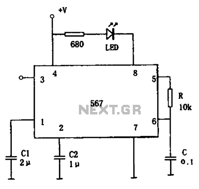
The FM demodulation circuit is illustrated in Figure 567. The FM signal is input at pin 3, and the demodulated signal is output from pin 5. The center frequency of the FM demodulation circuit is determined by the formula...

The output DC voltage of sensor SEN1 changes linearly in response to variations in relative humidity. This DC voltage is routed through resistors R1 and R2 to the analog-to-digital (A/D) converter chip U2. Resistor R4 is connected to ground,...

1999 Civic Wiring Diagram for Courtesy Lights Manual PDF. The 1999 Civic Wiring Diagram for courtesy lights provides a comprehensive visual representation of the electrical connections and components associated with the vehicle's interior lighting system. This schematic is essential for...

In the absence of light, photocells PC1 and PC2 exhibit high resistance, causing transistors Q1 and Q2 to remain off, which prevents the relay contacts K1 and K2 from closing. The battery B3 is connected through a potentiometer Rs,...
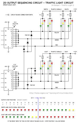
The current application involves the use of the VHDL hardware description language for designing a traffic light system controller circuit. This design is implemented within the Altera MAX PLUS EDA software environment, which facilitates compilation, simulation, and programming for...
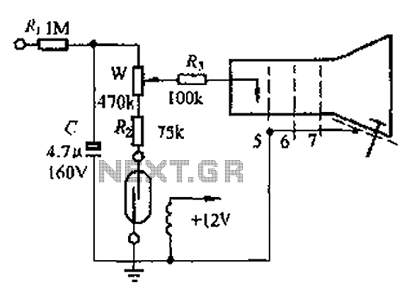
A reed switch is utilized in a TV highlights cancellation circuit. A brightness potentiometer is grounded in series with the reed switch. Under normal operation, the reed contact remains closed, allowing the capacitor C to charge to approximately 160V....
Warning: include(partials/cookie-banner.php): Failed to open stream: Permission denied in /var/www/html/nextgr/view-circuit.php on line 713
Warning: include(): Failed opening 'partials/cookie-banner.php' for inclusion (include_path='.:/usr/share/php') in /var/www/html/nextgr/view-circuit.php on line 713