
Metering circuit using PbS PbSe
The described infrared light detection circuit is essential for applications such as spectrophotometry, where precise measurement of light intensity in the infrared spectrum is critical. The circuit typically comprises an optical detector, which can be either a lead sulfide (PbS) or lead selenide (PbSe) photoconductor. These materials are chosen for their sensitivity to infrared wavelengths, making them suitable for various applications in optical sensing.
The operational principle of the circuit relies on the generation of a signal current (Is) when infrared light strikes the detector. The current produced is directly proportional to the intensity of the incoming infrared light. The essential resistance (Rd) of the optical detector plays a significant role in determining the overall sensitivity and performance of the circuit. The output voltage (Vo) from the amplifier is calculated using the formula Vo = Is·Rd·Rf/Ri, where Rf is the feedback resistance and Ri is the input resistance.
In the circuit design, careful selection of the feedback and input resistances is crucial to optimize the gain and bandwidth of the amplifier, thereby ensuring accurate signal amplification. The circuit may also include additional components such as capacitors for filtering and stability, as well as protection diodes to prevent damage from over-voltage conditions.
Overall, this infrared light detection circuit represents a fundamental building block for devices that require the measurement of light in the infrared spectrum, with applications ranging from environmental monitoring to industrial process control.This circuit canbeused for detecting infrared light, for example, it is used for detecting infrared band light signal in spectrophotometer. Amplifier output voltage Vo=Is·Rd·Rf/Ri wherein : Is-signal current; Rd-optical detector essential resistance Dector can bemade by lead sulphide (PbS) or lead selenide (PbSe), and at room temperature, PbS response..
🔗 External reference
Related Circuits
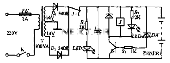
Bidirectional control is implemented for a motor to increase its operational degree. The motor can rotate in either direction with a current of 1A. A variable duty cycle multivibrator is utilized to achieve the construction and control of the...
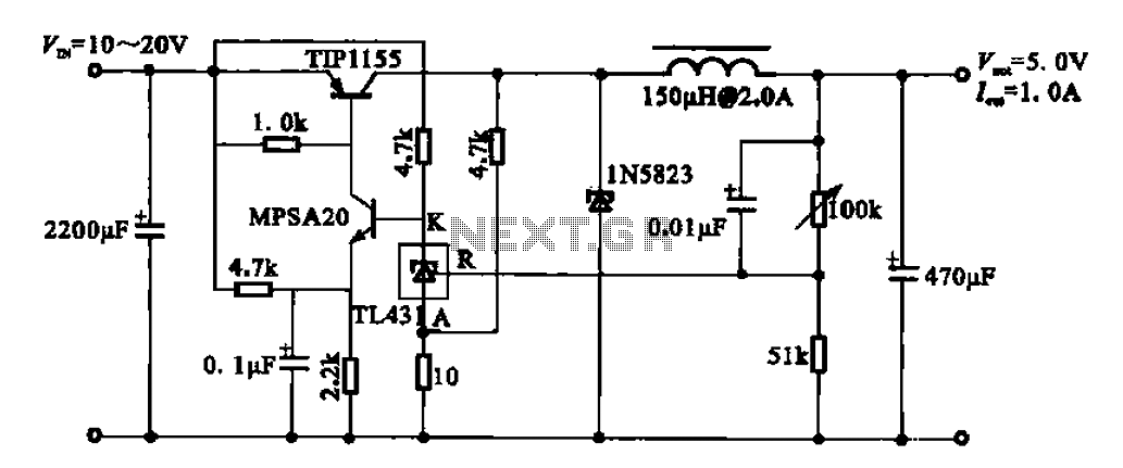
The 5V regulator circuit is designed to convert a DC input voltage ranging from 10V to 20V into a stable 5V output. This circuit features low power consumption and high efficiency. The 5V regulator circuit typically employs a linear voltage...
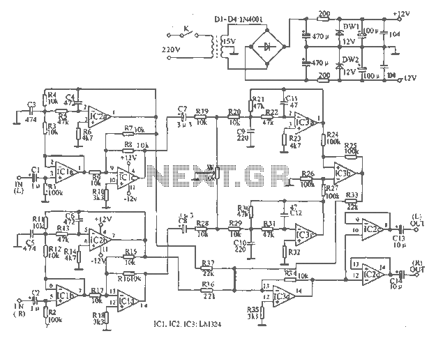
The tape output circuit processes the left and right channel signals through a first buffer amplifier. The output signal is split into two paths: one route directly connects to an amplifier for amplification, while the other route passes through...
This webpage outlines the radio transmitter unit that was part of the Cirrus One rocket mission in April 2001. The transmitter was included as a payload due to concerns about recovery challenges if the rocket drifted far downrange after...
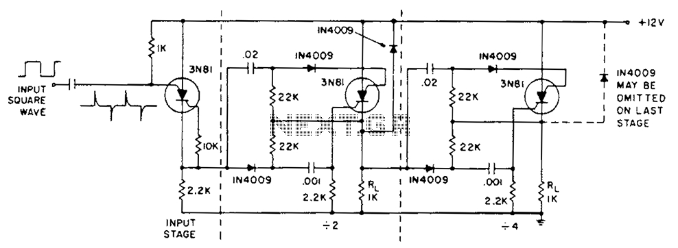
The circuit operation is initiated by a positive edge signal. The anodes of the triac switches are activated while the cathodes of the switches remain closed. A male-female IN4009 diode is utilized for positive transient suppression, ensuring that the...
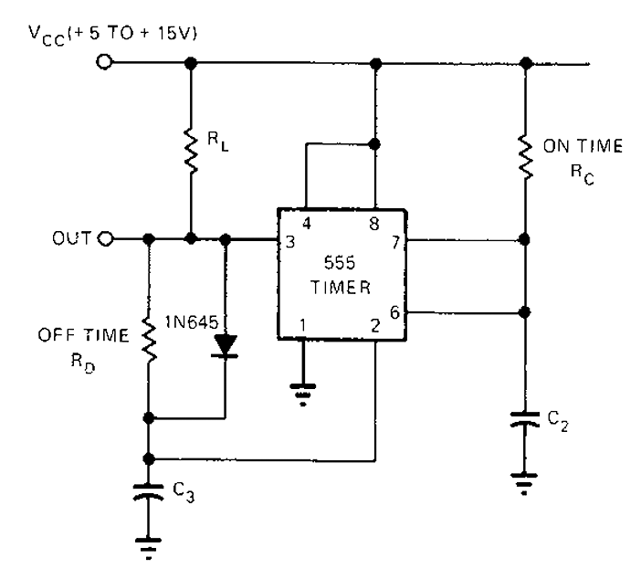
The 555 timer circuit has unsteady open and closing times that are independent of one another. One time constant is given by 1.1RcC2, while another time constant is defined as 1.1RcC3. The free-running period is the sum of these...