
honda xl100 electrical schematic
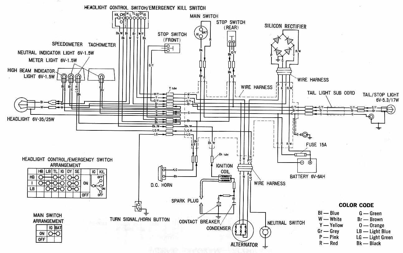
The Honda XL100 electrical schematic provides a comprehensive overview of the electrical connections and components utilized within the motorcycle. This schematic serves as a critical resource for understanding how various parts interact and function within the electrical system.
Key components depicted in the schematic include a silicon rectifier unit, which converts alternating current (AC) generated by the alternator into direct current (DC) for powering the motorcycle's electrical systems. The wiring harness is a crucial element that organizes and routes electrical connections between various components, ensuring efficient signal transmission and power distribution.
The tail light sub cable connects to the tail/stop light, which illuminates when the motorcycle is in operation, enhancing safety for the rider. The high beam indicator provides a visual cue to the rider when the high beam headlights are activated. Additional indicators, including the speedometer and tachometer, offer vital information regarding the motorcycle's speed and engine RPM, respectively.
Safety features are incorporated within the schematic, including the fuse for the headlight control switch and the emergency kill switch, which allows the rider to quickly disable the engine in case of an emergency. The stop switch is another safety mechanism that enables the rider to cut off the engine when necessary.
The battery serves as the primary power source for the electrical system, while the neutral switch indicates when the transmission is in neutral, allowing for safe starting of the engine. Other components such as the condenser, contact breaker, and spark plug are essential for the ignition system, ensuring proper engine operation.
Overall, the Honda XL100 electrical schematic is an invaluable tool for troubleshooting, maintenance, and modifications, providing a clear representation of the motorcycle's electrical architecture and facilitating a better understanding of its operational dynamics.Honda XL100 electrical schematic. Features: shows the connection between Honda parts. Component: Silicon rectifier unit, wiring harness, tail light sub cable, tail/stop light, high beam indicator, m light, speedometer, tachometer, fuse headlight control switch, emergency kill switch, switch, stop switch, battery, neutral switch, condenser, contact breaker, spark plug, Horn, indicators, headlights 🔗 External reference
Related Circuits
An article previously discussed connecting to the Raspberry Pi board from a Linux PC using the serial port. This time, the focus is on how to achieve the same connection using a Windows PC. In this case, a Windows...
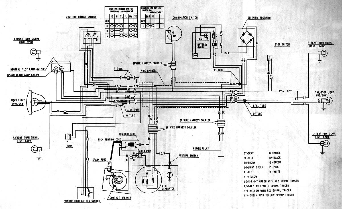
This circuit illustrates the electrical wiring diagram for the Honda S90, as detailed in the Haynes manual. It highlights the connections between various Honda components, including a fuse. The Honda S90 electrical wiring diagram serves as a vital reference for...
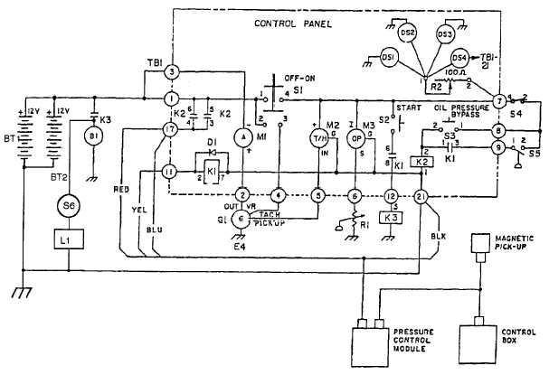
When both S1 and R2 are activated, current flows through each of the lamps connected in parallel to the rheostat. The current flow, and consequently the intensity of illumination, can be regulated by adjusting the effective voltage from the...
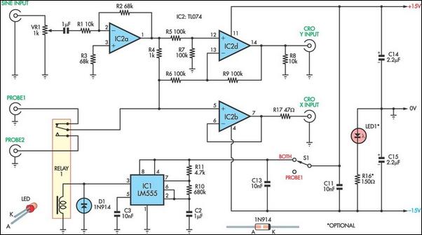
This unit utilizes a dual trace oscilloscope with X-Y functionality as a display to test and demonstrate the operation of circuits and components such as transistors, diodes, zener diodes, and both terminated and unterminated transformers. A low-frequency sine wave...
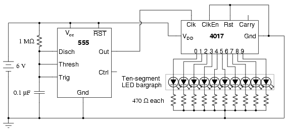
The following circuit illustrates a schematic diagram of an LED sequencer. This circuit is based on the 555 timer integrated circuit (IC). Features include a 555 timer circuit designed to debounce a mechanical switch, a 555 timer circuit to...
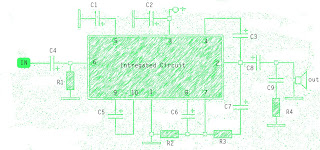
The amplifier circuit is well-suited for use in subwoofer speakers due to its robust performance. This circuit utilizes an integrated circuit (IC) based on the STK series. It can be employed in vehicles equipped with speakers or a subwoofer...