
Household appliances electric water heater temperature regulating circuit circuit
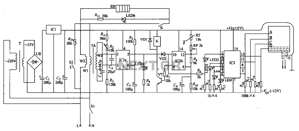
The power switch circuit (S1) operates with an AC 220V voltage that is stepped down by transformer T, rectified by UR, and subsequently filtered and regulated by IC1, producing a +12V output across C2. This voltage supplies power to the leakage protection, temperature control, water level indication, and anti-dry circuits. When the water temperature in the tank drops below 40°C (the lower limit), the voltage at pin IC2 is less than Vcc/3, causing a high output at the corresponding pin, which activates the transistor VT and engages the relay K. This action connects the electric heater (EH) to the power supply, turning on LED6. As the water temperature rises to 45°C (the upper limit), the voltage at pin IC2 drops, deactivating VT and releasing K, which stops the heating process and turns off LED6. The system cycles, maintaining the water temperature between 40°C and 45°C.
During normal operation, the current flowing through transformer windings W1 and W2 stabilizes, resulting in an induced voltage of 0V at winding W3. This keeps pin IC2 above 2Vcc/3, signaling normal operation with LED1 illuminated, indicating no leakage. If a leakage occurs, the current through windings W1 and W2 increases suddenly, causing a voltage to be induced in winding W3. This change leads to a drop in pin IC2 voltage, turning off LED1 and indicating a leakage fault. The conduction of diode VD2 causes pin IC2 to output a low signal, releasing K and cutting off power to EH, thus providing leakage protection. The button S2 serves as a leakage protection test. When pressed, it shorts the circuit through a resistor, inducing a voltage in winding W3, which causes LED1 to toggle its state, confirming the functionality of the leakage protection circuit.
The water level indicator circuit employs an electrode (AE) for level detection, along with resistors R1 and R2. Light-emitting diodes (LED2, LED5) and an analog electronic switch integrated circuit (IC3) are also part of this circuit. IC3 has four control terminals connected to water level detecting electrodes A, B, C, and D. When the water level rises to electrode D, it completes a circuit with the main electrode E (ground), causing the output of IC3 to go high and activating LED2. Simultaneously, IC2's output becomes high, allowing the temperature control circuit to engage EH (the electric heater) only when the water level is above electrode D to prevent dry operation. As the water level continues to rise to electrodes C, B, and A, the corresponding outputs of IC3 also go high, illuminating LEDs 3, 4, and 5. In the event of a leakage, diode VD2 conducts, ensuring IC2's output remains low, effectively shutting down the power supply to EH and maintaining safety.Electric water heater temperature control circuit, with water level indication, temperature and anti-dry, leakage power automatic protection function, safe and reliable. (1) Th e circuit electric water heater temperature control circuit from the power circuit, leakage circuit protection, temperature control circuit, a level indicative of anti-dry circuit, as shown in Figure 1-56. Power circuit from the power transformer T, rectifier bridge pile UR, filter capacitor c1, Cz and three-terminal voltage regulator integrated circuit lCl composition.
Leakage protection circuit current transformer TA, dual time-base integrated circuit IC2 (ICZa, ICZb) an internal timebase circuits and related peripheral components and parts. Temperature control circuit by the time-base integrated circuit IC2 double inside another time base circuit, thermistor RT, transistor VT, relay K, potentiometer RP and associated external components.
EH electric heater; LED1 work status indicator LEDs. LED6 electric heater indicator light-emitting diodes. (2) After the power switch circuit principle Sl, AC 220V voltage after T Buck, UR rectifier, C. After filtering and regulator IC1, at both ends of C2 + 12y generate voltage as leakage protection, temperature control, water level indication and anti-dry circuit power supply. Thousands of low temperature in the tank 40 (water temperature is set lower limit temperature), IC2 pin voltage is lower than V {i:/3, feet high output, the transistor VT conduction, the relay pull-K, its normally open contact connected to the electric heater EH energizes work, LED6 light.
When the water temperature is heated to 45t (set temperature upper limit temperature), 1C2 of a pin goes low, the VT end, K release, EH stop heating. LED6 extinguished. When the water temperature drops until less than 40, EH and start working, LED1 light, so the cycle, the tank temperature constant at 40 to between 45.
When the electric heater EH is working properly, the current flowing through the transformer winding WI TAs, W2 more stable operating current, the winding W3 on the induced voltage is 0, IC2 pin voltage is greater than 2Vcc:/3, pin voltage is low dry 2Vcc/3, feet high output, the light emitting diode LED1 lit, indicating EH normal operation, no leakage phenomenon. When EH leakage occurs, will lead to flow through the windings Wl TAs, W2 in operating current suddenly increases, resulting in a sense of winding W3 will be voltage, feet of IC2 goes high, pin goes low level, LED1 off, indicating the presence of EH leakage.
Meanwhile diode VD2 conduction, IC2 of ? pin goes low, a pin output low, the VT end, K release, the EHs power supply cut off, to achieve a leakage protection. S2 for the leakage protection test button. When the button is pressed, the horse Zouren resistor circuit, the winding Wl TAs, W2 in a short-circuit current, voltage is induced in the winding W3, lC2 the pin goes high, feet from the high variant low, LED1 lit by the state variable is off, indicating that the leakage protection circuit can play Bei electrical protection...
Water level indicator circuit with anti-dry south level detection circuit electrode AE, resistors horses, horse 2, Rl. Light emitting diode LED2, LED5 and analog electronic switch integrated circuit IC3 composition. 1C3 four control terminal ( feet, feet, feet and feet) water level detecting electrode, respectively, A - D is connected.
When the water tank, the water level rises to the electrode at D, the main electrode E (for the ground, and + f ,: connected) through the water and electricity Xi phase D then make the IC3 feet high, inside the feet to analog electronic switch is turned ON, the IC3 O pin goes high, indicating a low level light emitting diode l. ED2 lit, while ? feet of IC2 goes high, the temperature control circuit controls EH work (when the water level is below the electrode D, EH does not work, EH to prevent damage due to dry).
The water level continues to rise to the electrodes C, B, A when, IC3s feet, feet and legs have also changed to high level, the water level indicator LED LED3, LED4 and LED5 also have been lit. When leakage, diode VD2 conduction, so that the 1C2 ? pin goes low, a pin output low, the VT end, K release, the EHs power supply cut off, to achieve a leakage protection.
Related Circuits
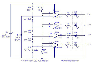
This circuit is a practical device that, when installed in a vehicle, displays the voltage of the car battery using an LED dot display. The meter circuit utilizes four comparators formed from a quad op-amp, specifically the LM324. The...
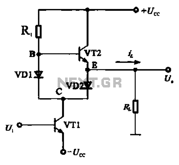
A Class AB output stage circuit is coupled with diodes, as illustrated in Figure 10-8. The static bias circuit for transistor VT1 (not shown) is adjusted so that the output at point E is at ground DC voltage UE....
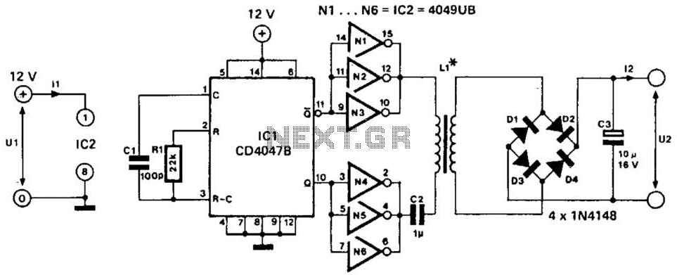
This low-power converter supplies approximately 100 mW of DC power to a load and is useful for isolating or deriving DC voltages. It operates at a frequency of around 200 kHz. The inductor is wound on a 22-mm diameter,...
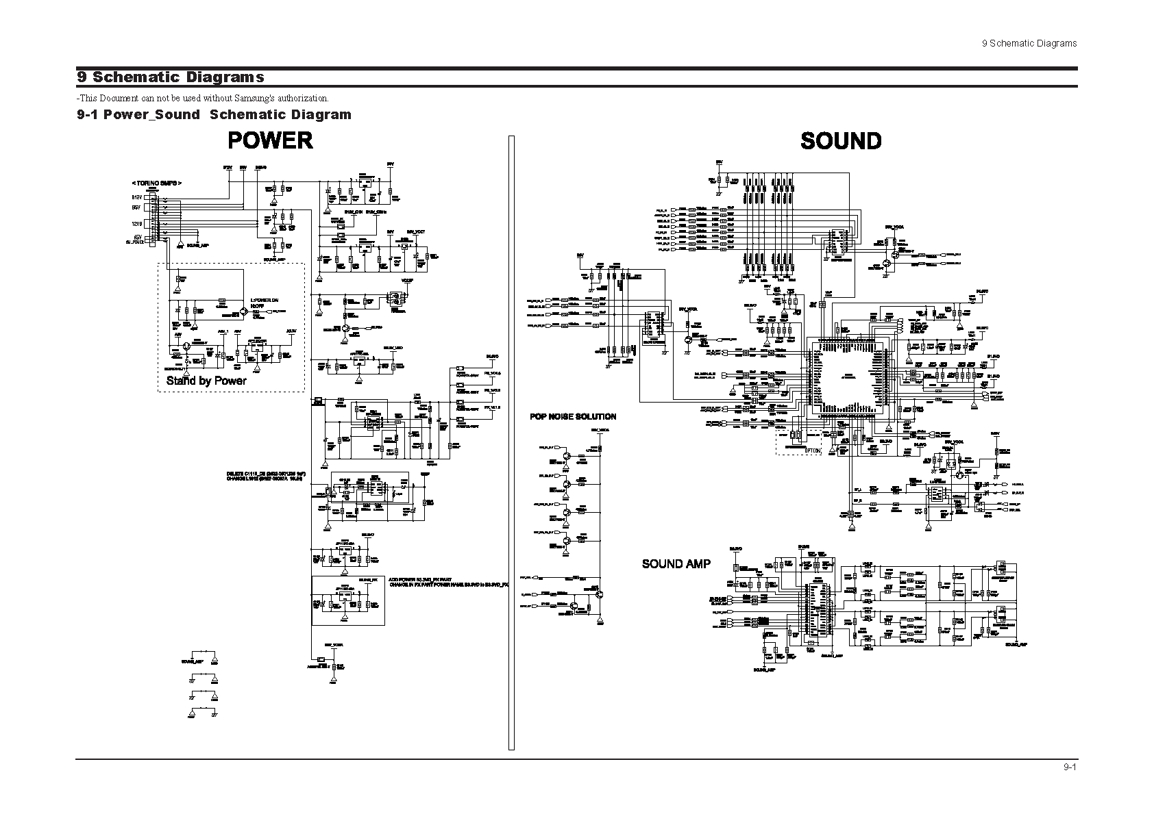
Samsung C3330 Circuit Diagram Download Manual PDF Download. The Samsung C3330 circuit diagram serves as a comprehensive reference for understanding the electronic architecture of the device. This schematic provides detailed insights into the interconnections between various components, including the microcontroller,...
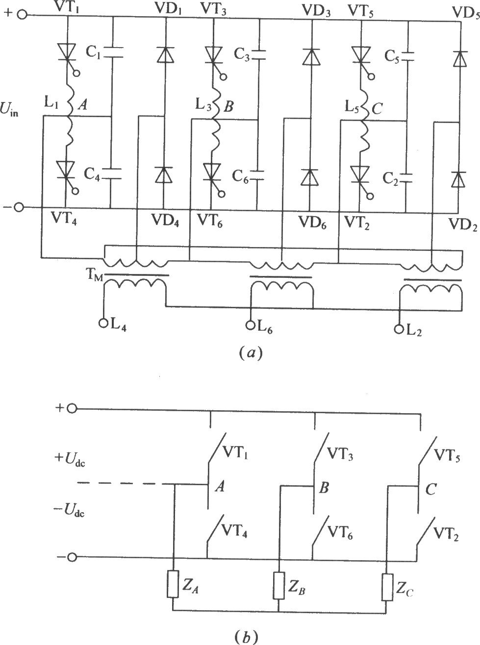
The figure illustrates a traditional three-phase bridge inverter circuit. Components VT1 to VT6 represent thyristors, while L1 to L6 are commutation reactors. Capacitors C1 to C6 serve as commutating capacitors, and the thyristor shut-off circuit is composed of two...
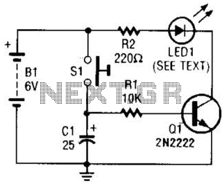
Used as a 10-second momentary illuminator, this circuit can be useful in other applications as well. Pressing SI charges CI, which holds Q1 on and keeps the LED lit for about 10 seconds. The circuit described functions as a momentary...