
Three phase bridge type inverter circuit diagram
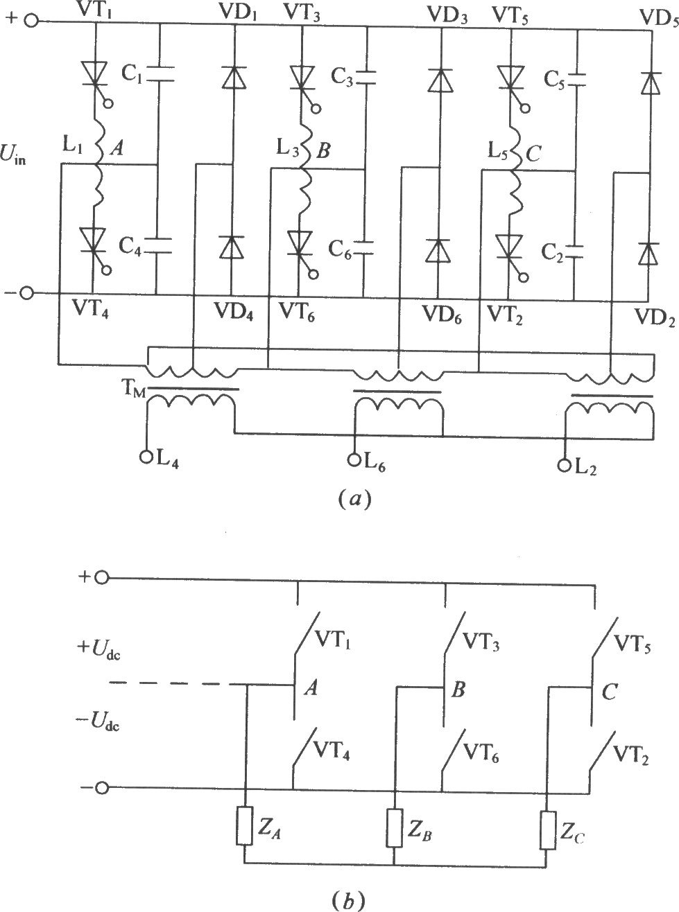
The three-phase bridge inverter circuit is a critical component in various applications such as motor drives, renewable energy systems, and power conversion technologies. The configuration employs six thyristors arranged in a bridge format, allowing for the conversion of three-phase AC input into a controlled DC output. The thyristors (VT1 to VT6) are semiconductor devices that can control the flow of current, enabling the inverter to switch the output voltage polarity and generate a variable frequency output.
Commutation reactors (L1 to L6) are integral to the circuit, providing the necessary inductance to facilitate the commutation process, which is essential for turning off the thyristors. These reactors help to manage the transient conditions that arise during switching, ensuring stable operation and reducing voltage spikes that could damage the components.
The commutating capacitors (C1 to C6) work in conjunction with the reactors to store and release energy, aiding in the proper turn-off of the thyristors. The feedback diodes (VD1 to VD6) provide a path for the current to flow when the thyristors are turned off, preventing reverse voltage issues and ensuring safe operation.
The thyristor shut-off circuit, which consists of two parts, is crucial for managing the timing of the thyristor operation. This circuit ensures that the thyristors are turned off appropriately to prevent unwanted conduction and to maintain efficient operation of the inverter.
Overall, this three-phase bridge inverter circuit exemplifies a robust design capable of handling varying loads while providing reliable power conversion from AC to DC. The careful selection and arrangement of components are essential for achieving optimal performance and longevity of the system.As shown in the figure is the traditional three-phase bridge type inverter circuit:VT1?VT6 is thyristor, L1?L6 is commutation reactor, C1?C6 is commutating capacitor, the thyristor shut-off circuitconsists of the two parts. VD1?VD6 is feedback diode. According to the work principle of the thyristor, it based on the 3-phaseAC inputpower supply, If the thyr..
🔗 External reference
Related Circuits
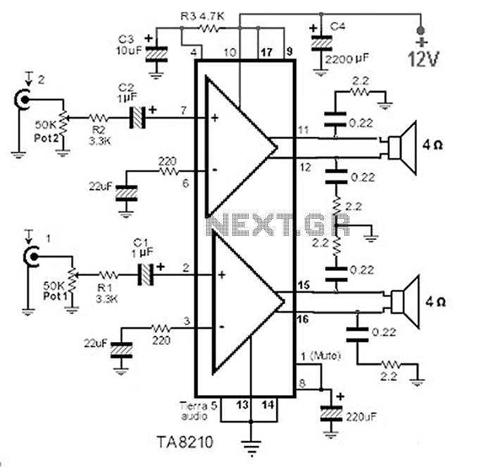
This circuit consists of a 2 x 22 watt BTL amplifier utilizing the IC TA8210AH. It functions not only as an automobile amplifier but is also suitable for low-frequency sound applications, particularly in high-fidelity audio systems, due to its...

This topic will be locked and will display all of the circuits and some photos of the devices being worked on in the Joule Thief topic. This process will take some time, so patience is appreciated. If any errors...
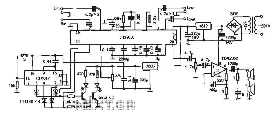
The surround processing section C1891A is a product from Sony Corporation of Japan that features a four-dimensional home theater surround processing circuit. It includes a parent roll phase-shifting circuit and a matrix surround sound amplifier. Additionally, it provides three...
Access to the resistors was available, and measurements indicated an open circuit when disconnected from any ground or input source. The circuit in question involves resistors that have been verified for accessibility. When measured in isolation—meaning they are not connected...
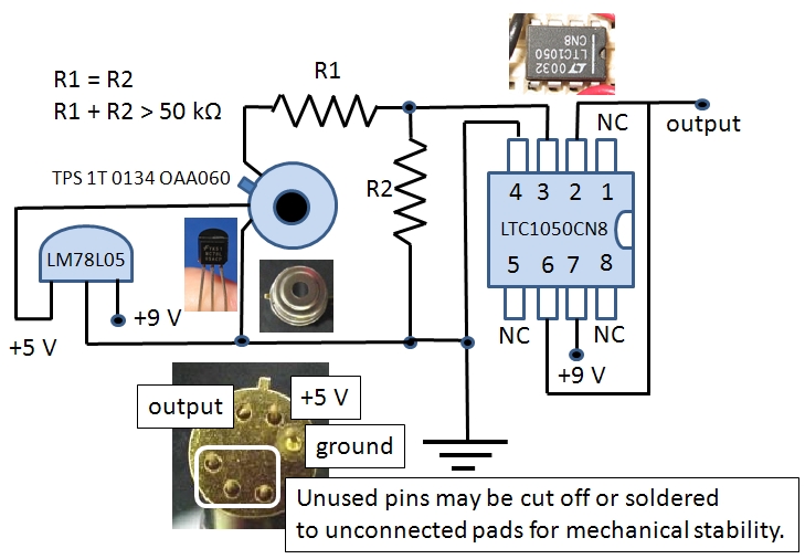
The Excelitas TPS 1T 0134 OAA060 thermopile sensor is a self-contained module that includes a built-in operational amplifier. The designation A2TPMI 334 OAA 60 is used in this document due to its previous identification under the PerkinElmer part number...
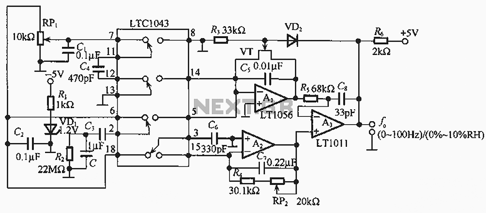
The humidity/frequency conversion circuit operates similarly to the previously mentioned humidity sensors. At a humidity level of 76%, the equivalent capacitance is 500 pF, with a capacitive relative humidity variation rate of +1.7 pF/%. The circuit includes an integrating...
Warning: include(partials/cookie-banner.php): Failed to open stream: Permission denied in /var/www/html/nextgr/view-circuit.php on line 713
Warning: include(): Failed opening 'partials/cookie-banner.php' for inclusion (include_path='.:/usr/share/php') in /var/www/html/nextgr/view-circuit.php on line 713