
how atx power supply works
The ATX power supply is a critical component in modern computer systems, providing the necessary electrical power to various components such as the motherboard, CPU, and peripheral devices. The design of ATX power supplies adheres to specific standards set by Intel, ensuring compatibility and efficiency across different systems.
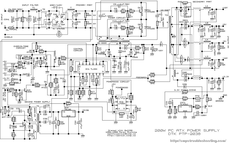
An ATX power supply typically converts alternating current (AC) from the wall outlet into direct current (DC) at various voltage levels required by computer components. The standard voltage outputs include +3.3V, +5V, +12V, and -12V, which are utilized by different parts of the computer.
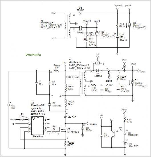
In a 200 Watt PC power supply example, the power supply unit (PSU) consists of several key components: a transformer, rectifiers, filters, and voltage regulators. The transformer steps down the AC voltage to a lower level, which is then rectified using diodes to convert it from AC to DC. After rectification, the DC output is smoothed through filtering capacitors to reduce voltage ripple. Finally, voltage regulators ensure that the output voltages remain stable and within the specified limits, even under varying load conditions.
The ATX power supply features a 24-pin connector that interfaces with the motherboard, along with additional connectors for components such as the CPU and graphics cards. The power supply also includes protective features such as over-voltage, under-voltage, and short-circuit protection to safeguard both the PSU and the connected components.
In summary, the operation of an ATX power supply involves a sequence of processes that convert and regulate electrical power, ensuring that all components of a computer receive the appropriate voltage and current for optimal performance.A step by step guide about how ATX power supply works with an example of a 200 Watt PC Power Supply function.. 🔗 External reference
Related Circuits
To celebrate the hundredth design posted to this website and to fulfill the requests of many correspondents wanting an amplifier more powerful than the 25W MosFet, a 60 - 90W high-quality power amplifier design is presented here. The circuit...
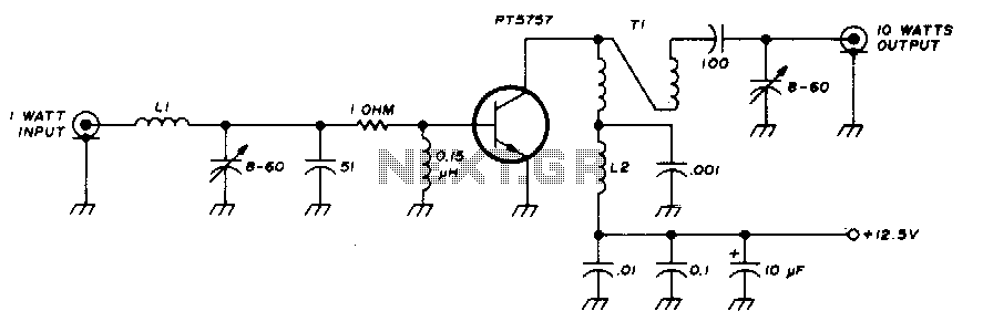
This 10-watt, 144-MHz power amplifier utilizes a TRW PT5757 transistor. The inductor LI consists of 4 turns of no. 20 enameled wire with a 3/32" inner diameter, while inductor L2 comprises 10 turns of no. 20 enameled wire with...
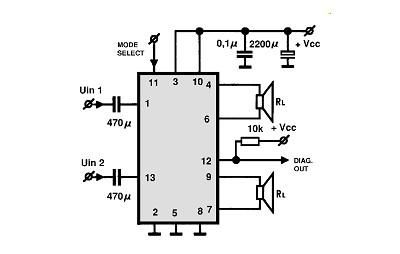
A simple Class B power amplifier can be constructed using the TDA8560 audio integrated circuit (IC). The TDA8560 amplifier features an internally fixed voltage gain, ensuring excellent channel balance. This audio amplifier project is capable of delivering dual 40-watt...
High Current Variable Power Supply Circuit Diagram. The widely used variable voltage regulator IC LM317 can handle a maximum current of only 1 ampere, making it unsuitable for applications requiring a high current variable power supply. The design of a...
The circuit is constructed using two 555 timer integrated circuits, designated as U1 and U2. U1 is configured as a variable duty cycle oscillator with a fixed time period of approximately 0.1 seconds. The duty cycle can be adjusted...
This application note demonstrates a simple 8-direction digital compass application utilizing Zilog's Z8 Encore!® MCU and an external compass sensor hardware. Communication ports are provided for the digital compass to receive commands and send status via the I2C bus...