
How should I wire up the circuit to connect a TSOP4838 (Radio Shack 276-64) infrared receiver to an Arduino
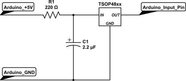
To implement this circuit effectively, it is essential to ensure proper connections and component selection. The 200 Ohm resistor serves to limit the current flowing into the data line, protecting the microcontroller from potential damage due to excessive current. When using a 3.3V supply, the resistor should be connected between the power line and the data line, with the other end of the data line connected to a digital pin, such as pin #2 on the Arduino.
In the example provided in the datasheet, the inclusion of a 100 Ohm resistor and a 4.7 microfarad capacitor suggests a design consideration for stability and noise reduction. The capacitor acts as a filter, smoothing out fluctuations in the power supply and providing transient response improvements. When connecting Vs to the 3.3V output of the Arduino, it is advisable to include the capacitor to ensure stable operation, especially if the circuit will be subjected to varying loads or if the data line experiences high-frequency switching.
The circuit schematic should clearly represent these connections: the 200 Ohm resistor in series with the data line, the capacitor connected in parallel between Vs and ground, and the digital pin connection. Proper labeling of components and values on the schematic will facilitate understanding and implementation. Additionally, if the design experiences issues with signal integrity or stability, experimenting with different capacitor values may yield beneficial results.All you need to do is supply a resistor (I used 200 Ohms, with a 3. 3V supply) to the power line, GND it, then connect the data line to one of your digital pins (I used pin #2)". However, the datasheet shows an example circuit with a 100 Ohm resistor connected to Vs along with a 4.
7 micro Farad capacitor connected between Vs and GND. I`m guessing that I should connect Vs to the 3. 3V output on the Arduino and use a 200 Ohm resistor, but do I need a capacitor 🔗 External reference
Related Circuits

The circuitry of the Regency exhibits several unique characteristics. Notable features include the self-oscillating mixer stage, the base bias voltage of the second IF stage derived from the AF power stage, an unusual IF frequency of 262 kHz, and...

The following circuit illustrates a Wireless Car Alarm Circuit Schematic Diagram. Features include the ability to detect sounds within a 20-meter radius, a 1/16 wavelength antenna, and the capability to transmit radio signals up to 2 kilometers. Q1 serves...
Government data sets available online are often sourced from major metropolitan areas or infrastructural centers. With an easy-to-follow introduction to new software and technologies, the urban sensor kit allows anyone to obtain location-specific information and share it with a...
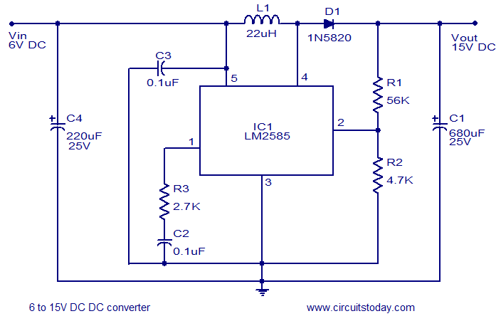
A simple and efficient 6 to 15V boost/step-up DC to DC converter based on IC L2585. This voltage converter circuit requires few external components. The circuit utilizes the L2585 integrated circuit, which is designed for high-efficiency voltage boosting applications. The...
An electromagnetic vibration table or feeder is designed to move small objects along a specific track or cylindrical path through forced vibrations. This device can be custom-built to facilitate the movement of items along a rail tube. The vibration...

The circuit depicted in Figure 11-14 utilizes a unidirectional thyristor within liquid level automatic control systems. It incorporates electrodes that serve as sensing elements for detecting the level of water or other conductive liquids. The circuit features a current...