
6V to15V DC to DC converter using LM2585 wired in the boost mode
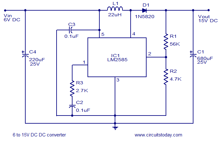
The circuit utilizes the L2585 integrated circuit, which is designed for high-efficiency voltage boosting applications. The L2585 operates by converting a lower input voltage (ranging from 6V to 15V) to a higher output voltage, making it suitable for various applications where higher voltage levels are required from a lower voltage source.
The essential components of this circuit include the L2585 IC, an inductor, a diode, and capacitors. The inductor is used to store energy when the switch inside the L2585 is closed and releases it when the switch opens, effectively stepping up the voltage. The diode is placed in the output path to prevent backflow of current, ensuring that the output voltage remains stable. Capacitors are used at the input and output to filter voltage ripples and stabilize the output voltage.
In terms of configuration, the circuit requires careful selection of the inductor and capacitors to match the desired output voltage and current specifications. The feedback mechanism within the L2585 regulates the output voltage by adjusting the duty cycle of the internal switching, ensuring efficient operation across varying load conditions.
This boost converter circuit is particularly advantageous in battery-powered applications where maximizing the available energy from lower voltage sources is critical. Its simplicity and efficiency make it a preferred choice for powering devices that require a higher operating voltage without the need for complex circuitry.A simple and efficient 6 to 15V boost/stepup dc to dc converter based on IC L2585. This voltage converter circuit requires few external components.. 🔗 External reference
Related Circuits
This device listens to conversations and then interjects words and phrases at inappropriate times. I got this box at a local thrift store for $1.50. It has a nice hinged top and a place to insert a panel with...
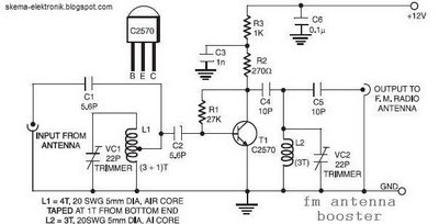
The coil L2 is tapped at the first turn from the ground lead side and is similar to coil L1, but consists of only three turns. The pin configuration of the transistor 2SC2570 is illustrated in the FM antenna...
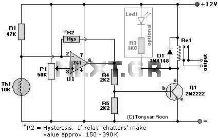
The following page outlines detail information on how to step by step design a Simple Heat Sensor Circuit. This circuit design utilized LM741 as the operational amplifier. More: Circuit Parts/Components List: Re1 = 12V relay R1 = 47K R2...
Switching regulator subsystems are designed for use as DC to DC converters. The 3V to 40V DC converter circuit utilizes switching regulators, which are increasingly favored over linear regulators due to the demand for higher conversion efficiency in modern...
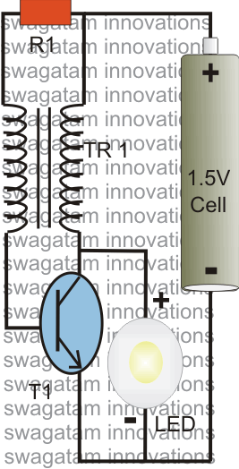
The post explains a simple 1 watt LED driver circuit using a single 1.5 V penlight cell through the joule thief concept. The coil may be wound over a T13 toroidal ferrite core using 0.2 mm or 0.3 mm...
A novice in circuit creation is utilizing a 12V battery regulated to 2mA with an LM334Z current regulator. Documentation for the current regulator is available. The LM334Z is a versatile current regulator that can be used in various applications requiring...