
How to amplify a square wave cheaply

To achieve the desired amplification of the signal generated for the piezo disk, a high-voltage amplifier circuit can be implemented. This circuit must be capable of taking the 10 V input signal and increasing it to the required output levels of 50 V or 100 V, depending on the specific application needs.
A suitable configuration for this purpose could involve using an operational amplifier (op-amp) in a non-inverting amplifier configuration, but it must be selected to handle high voltage outputs. The op-amp should be chosen based on its voltage rating, bandwidth, and slew rate to ensure it can effectively amplify the 100 Hz signal without distortion.
In addition to the op-amp, a power supply capable of providing the necessary voltage levels will be required. This power supply should be well-regulated to prevent fluctuations that could affect the performance of the piezo disk.
To protect the circuit and the piezo element from potential damage due to overvoltage, it is advisable to include a feedback mechanism that monitors the output voltage and adjusts the gain accordingly. This can be accomplished using a voltage divider in the feedback loop, allowing for precise control over the amplification factor.
Additionally, proper filtering should be considered to eliminate any noise from the signal generator and maintain the integrity of the output waveform. Capacitors can be added to the circuit to filter high-frequency noise, ensuring that the amplified signal remains clean and stable.
Finally, it is essential to ensure that all components used in the circuit are rated for the maximum output voltage to prevent breakdown and ensure reliability during operation. Proper heat dissipation methods should also be implemented, as high-voltage applications can generate significant heat in the components.I am driving a piezo disk at 100 Hz (or less) and am limited by the output of my signal generator to 10 V. I wish to amplify that to 50 or even 100 Volts. How to do .. 🔗 External reference
Related Circuits
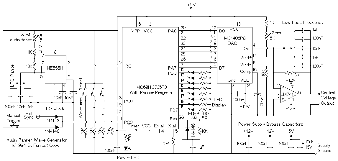
This device is a microprocessor controlled waveform generator that can be used for driving a voltage controlled stereo panner for music applications. Panning is simply the movement of a mono audio signal between the left and right channels of...
The objective is to design a square-wave generator with an output range of 0 to +5V. Additionally, the design should allow for the modification of the signal to enable adjustment of the duty cycle of the pulse (PWM). The square-wave...
A symmetrical millivolt peak-to-peak triangle waveform can be generated by the circuit illustrated in the schematic diagram below. This circuit is equipped with... This circuit employs an operational amplifier (op-amp) configured in an integrator setup to produce a triangle waveform. The...
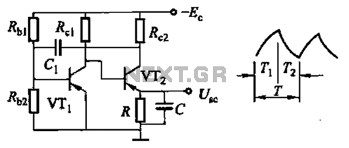
Common non-sinusoidal oscillator circuit, waveform and frequency formula - sawtooth oscillator - use multivibrator. The sawtooth oscillator is a type of non-sinusoidal waveform generator that produces a triangular or sawtooth-shaped output signal. This oscillator is commonly utilized in various applications,...
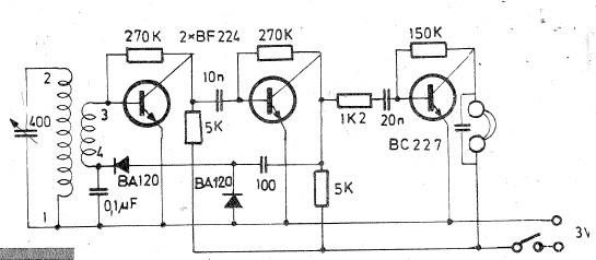
Oscillating circuits (coils) are constructed on a ferrite bar. For long wave reception, winding "1-2" consists of 135 turns, while winding "3-4" consists of 20 turns. For medium wave reception, winding "1-2" has 75 turns, and winding "3-4" has...
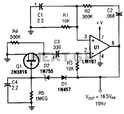
This Wien-bridge sine-wave oscillator utilizes a 2N3819 as an amplitude stabilizer. The 2N3819 functions as a variable-resistance element within the Wien bridge. The Wien-bridge oscillator is a type of electronic oscillator that generates sine waves. It employs a bridge circuit...