
Simple B+ delay circuit for tube power amp
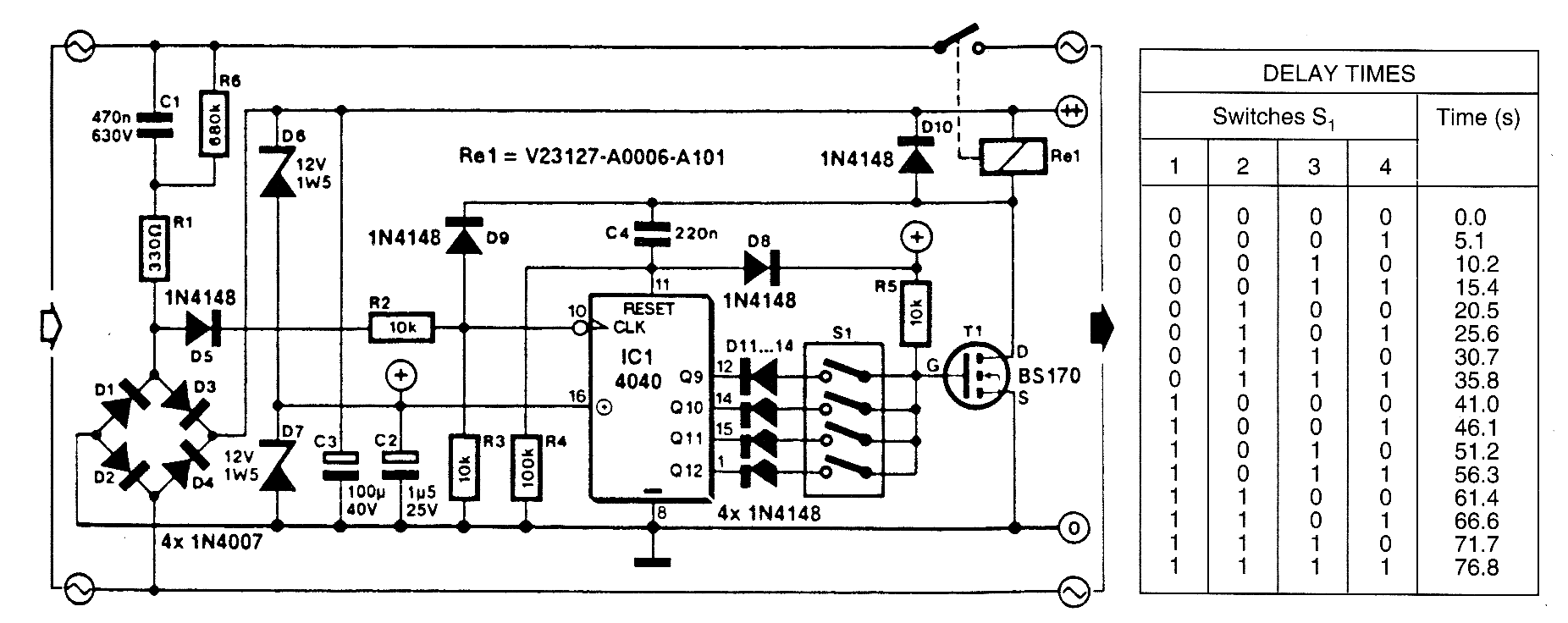
The modification to the RC delay circuit involves adjusting the resistor-capacitor (RC) time constant to achieve a shorter discharge time. This can be accomplished by either reducing the resistance or the capacitance in the circuit. The time constant (τ) is defined as τ = R × C, where R represents resistance in ohms and C represents capacitance in farads. By decreasing either of these values, the discharge time can be minimized, leading to a faster reset of the circuit.
For practical implementation, consider using a potentiometer in place of a fixed resistor. This allows for fine-tuning of the resistance value, enabling precise control over the discharge time. Additionally, selecting a capacitor with a lower capacitance value will also contribute to a quicker discharge. However, care must be taken to ensure that the new values do not adversely affect the circuit's performance or stability.
When modifying the RC delay circuit, it is essential to analyze the impact of these changes on the overall functionality. The discharge curve should be examined to ensure that it meets the desired specifications. Furthermore, it may be beneficial to simulate the circuit using software tools to visualize the effects of the modifications before implementing them in a physical prototype.
In summary, the modification to achieve a shorter discharge time in RC delay circuits can enhance the responsiveness of the system, making it suitable for applications where rapid circuit restarts are necessary.There is a mod to the RC delay circuits some of you may want to consider. If you wish to have a shorter discharge time so that the circuit restarts.. 🔗 External reference
Related Circuits

This circuit is particularly beneficial for hobbyists using a breadboard to experiment with ideas, as well as those employing a simple homemade DC power supply that consists of a transformer, rectifier, smoothing capacitor, and protective fuse, specifically one lacking...

The schematic for this project is not overly complex; however, it is crucial to understand the circuit board and its operation due to the high voltages generated. Below is a rough draft schematic of the camera used for this...
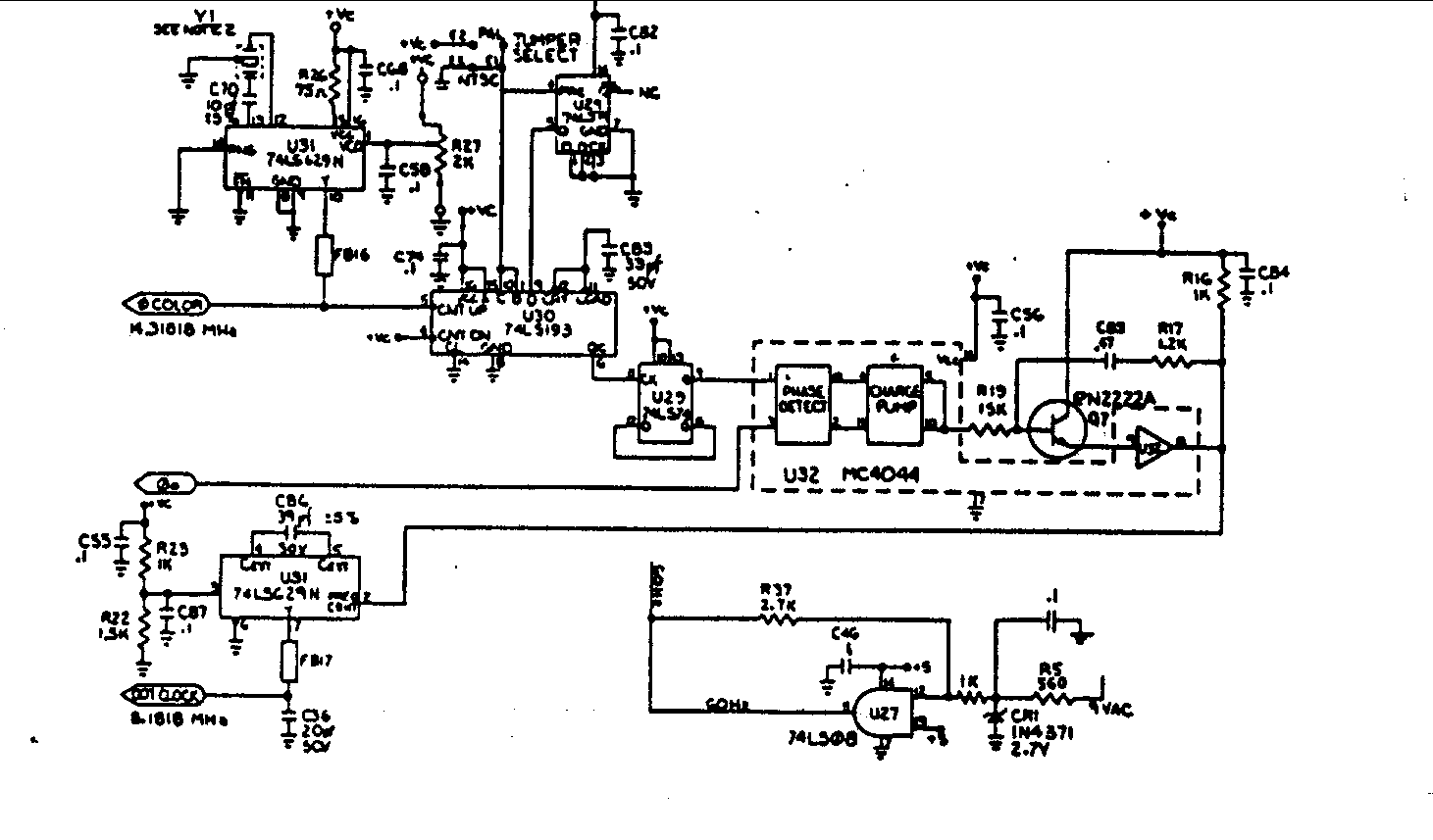
Crystal Y1 generates a fundamental frequency clock signal of 14.31818 MHz. U31 is a Dual Voltage Controlled Oscillator (VCO) that produces a 14.31818 MHz clock signal, referred to as the color clock, at pin 10. The output frequency can...
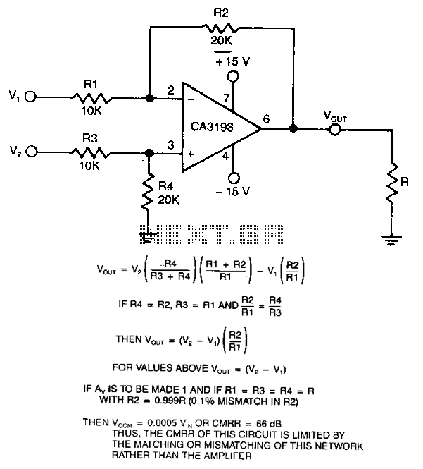
This differential amplifier utilizes a CA3193 BiMOS operational amplifier. It serves as a classical differential input-to-signal-ended output converter, which, when paired with a low-resistance signal source, will sustain a high common-mode rejection ratio (CMRR), provided that R1 equals R3...
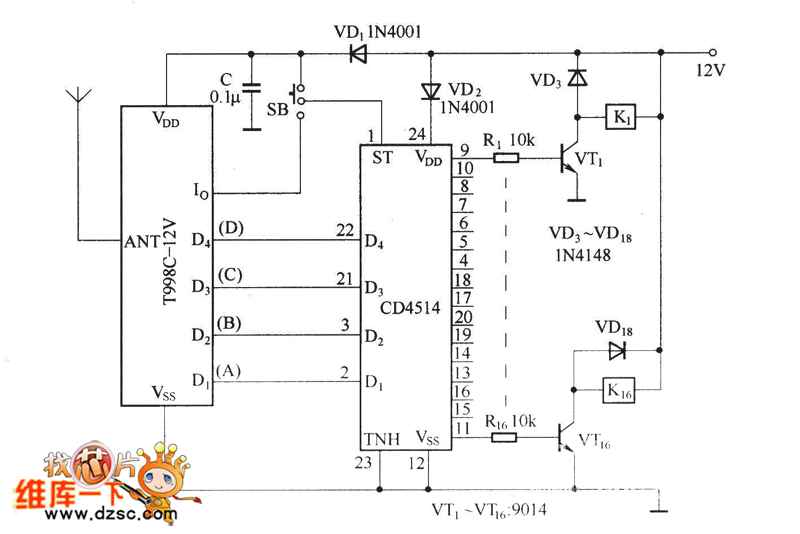
The circuit functions as both a latch output and a non-latched output. The control switch, labeled SB, governs the operation. When both SB and VDD are activated, the circuit enters the latch output state, allowing the sixteen output terminals...
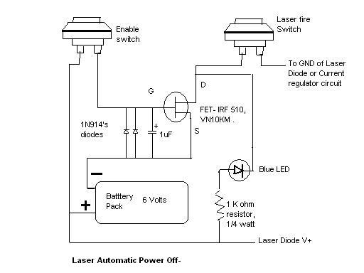
Here is the automatic laser power-off circuit schematic. This circuit features a visible power indication. In this case, the ground is connected on one side. The automatic laser power-off circuit is designed to enhance safety and efficiency in laser applications...
Warning: include(partials/cookie-banner.php): Failed to open stream: Permission denied in /var/www/html/nextgr/view-circuit.php on line 713
Warning: include(): Failed opening 'partials/cookie-banner.php' for inclusion (include_path='.:/usr/share/php') in /var/www/html/nextgr/view-circuit.php on line 713