
5v dual power supply
The circuit design begins with a center-tapped transformer that is capable of handling either 230V AC or 110V AC input voltages, providing a secondary output of 9V-0-9V. The center tap allows for a dual output, which can be beneficial for applications requiring both positive and negative voltages relative to the center tap.
Following the transformer, the AC voltage is routed to a bridge rectifier composed of four 1N4001 diodes. Each diode is rated for a maximum reverse voltage of 50V and a forward current of 1A, making them suitable for this application. The diodes are arranged in a bridge configuration to convert the alternating current (AC) into direct current (DC). This configuration allows for full-wave rectification, which improves the efficiency of the power conversion process by utilizing both halves of the AC waveform.
After rectification, the output voltage is still pulsating DC, which requires smoothing to provide a stable DC voltage. A 2200μF electrolytic capacitor rated at 25V is employed to filter the rectified output. This large capacitance value helps to reduce voltage ripple, providing a more constant DC voltage level. The capacitor charges during the peaks of the rectified voltage and discharges during the troughs, thereby smoothing out the fluctuations.
In addition to the primary filtering capacitor, several smaller decoupling capacitors are strategically placed throughout the circuit. These capacitors serve to filter high-frequency noise and transients that may be present in the power supply, ensuring stable operation of the connected load. The selection of these decoupling capacitors is critical for maintaining the integrity of the power supply, especially in sensitive electronic applications.
Overall, the described circuit effectively converts high-voltage AC mains power into a stable low-voltage DC output suitable for various electronic applications, ensuring reliable performance through careful component selection and arrangement.The circuit is using a 230V AC OR 110V AC to 9V-0-9V step down center tapped transformer to step down the mains voltages. Four 1N4001 diodes are used for rectification of the AC voltage to DC. A 2200uF / 25V electrolytic capacitor is used the filter the voltage coming from the diodes and other capacitors are used for decoupling.
🔗 External reference
Related Circuits
The circuit is divided into two sections: the isolated external loop connected to the remote interface connector on the front of the power supply unit (PSU) and the non-isolated inner loop connected to the high-tension (AC line) supply. The...
Following a hunch, the author discovered (or re-discovered?) that all plants carry an electric charge relative to the ground. This charge is more or less constant regardless of the size of the plant - a kind of "background voltage"...
The ICM7226 is a fully integrated Universal Counter and LED Display driver. It combines a high-frequency oscillator, a decade timebase counter, an 8-decade data counter and latches, a 7-segment decoder, digit multiplexer, and segment and digit drivers, which can...
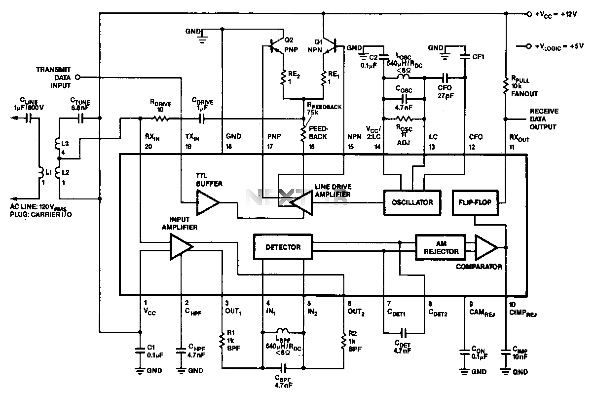
In the 100-kHz application, the coupling network feeds into the receiver section located at the bottom of the chip. The external components are summarized later. The receive data output is pulled up via a resistor (RPuLL) of approximately 10...
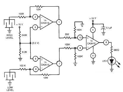
This liquid level sensor electronic circuit diagram utilizes a common CA3410 operational amplifier integrated circuit (IC). The sensor employs two plate sensors (or probes), one designated for detecting high liquid levels and the other for low liquid levels. If...
The first schematic is designed for individuals who exclusively purchase electronic components from Radio Shack. It allows for a straightforward shopping experience, enabling one to acquire all necessary parts in-store. For the heat sink, it is recommended to visit...
Warning: include(partials/cookie-banner.php): Failed to open stream: Permission denied in /var/www/html/nextgr/view-circuit.php on line 713
Warning: include(): Failed opening 'partials/cookie-banner.php' for inclusion (include_path='.:/usr/share/php') in /var/www/html/nextgr/view-circuit.php on line 713