
how to build a 2KVA inverter circuit diagram
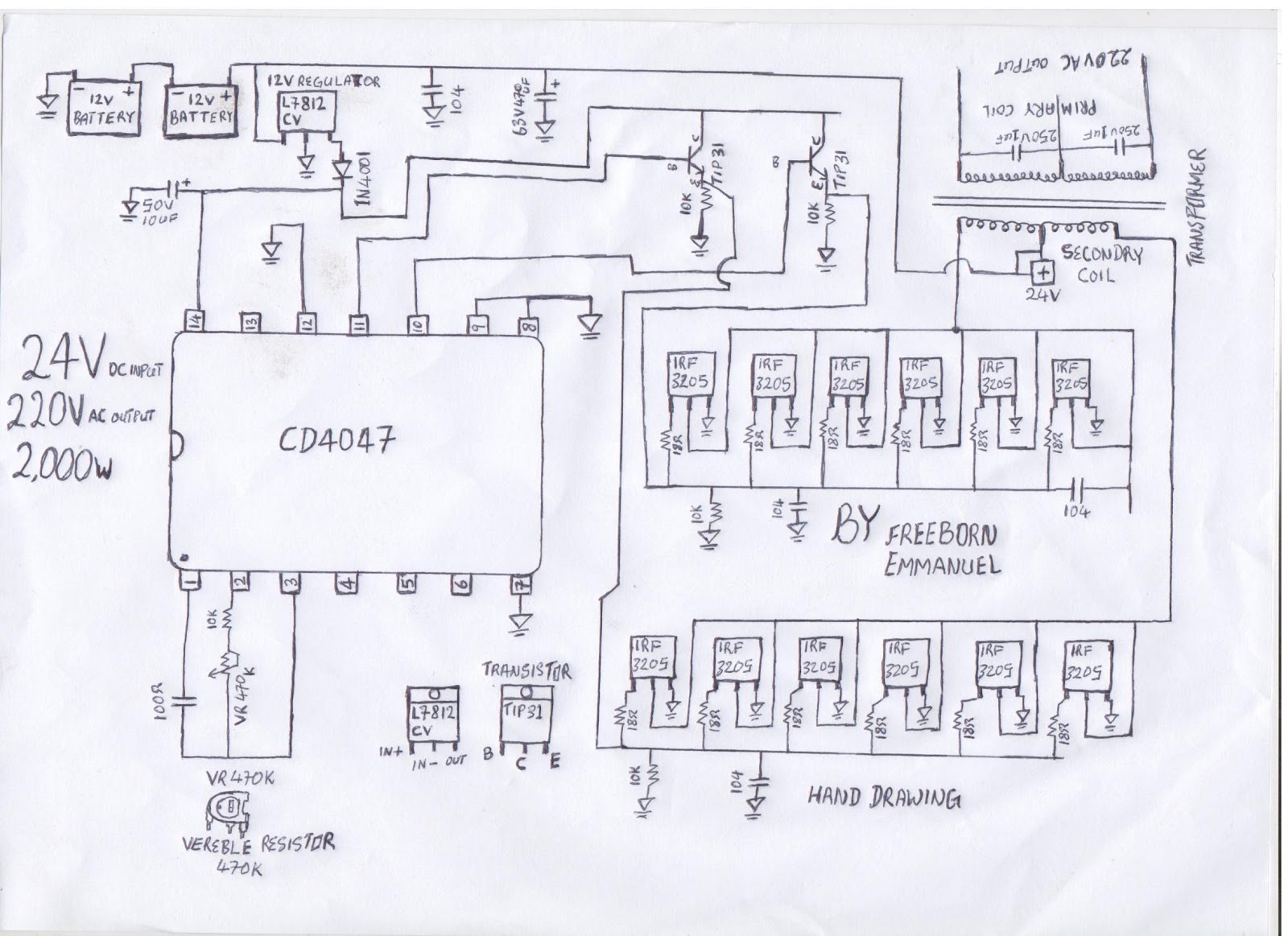
The modified square wave inverter circuit operates by converting direct current (DC) into alternating current (AC) using a transformer. The circuit's core component is the transformer, which is responsible for stepping up the voltage to a suitable level for powering household appliances. The inverter's design allows for frequency adjustment through the variable resistor (VR 470k), which alters the timing of the switching elements in the circuit, thereby modifying the output frequency.
The inverter employs a solid transformer, which is more efficient compared to chopper-based designs. This type of transformer typically consists of a core made from magnetic material, with primary and secondary windings. The primary winding is connected to the DC power source, while the secondary winding delivers the AC output. The winding configuration and the number of turns in each winding are critical for determining the output voltage and current capacity of the inverter.
To ensure optimal performance, the transformer must be carefully wound according to specific guidelines. The wire gauge, number of turns, and core material all contribute to the efficiency and effectiveness of the inverter. A well-designed transformer will minimize losses, allowing the inverter to operate efficiently without excessive battery drain.
Additionally, the circuit may include protective components such as fuses or circuit breakers to prevent damage from overcurrent conditions. Capacitors may also be used to filter the output, smoothing out the waveform and reducing electromagnetic interference (EMI), which can be particularly important when powering sensitive electronic devices.
Overall, this modified square wave inverter circuit provides a cost-effective solution for converting DC to AC, making it suitable for various applications in residential settings. The ability to adjust the output frequency enhances its versatility, allowing it to power a range of appliances while maintaining energy efficiency.the diagram is a modify square wave inverter circuit diagram, and if you adjust the frequency by adjusting or turning the frequency resistor (VR 47Ok) the inverter output frequency can be strong enough to power a freezer compressor and some other electronics appliances in a living room. the circuit dont drain battery so fast and its very cheap to design. the inverter is not a chopper transformer circuit base inverter it is a solid transformer base inverter, i will take time to arrange how you can wind the transformer. 🔗 External reference
Related Circuits
The circuit is based on a single operational amplifier integrated circuit designed to produce a modular preamplifier that operates in Class A configuration. The modular preamplifier circuit utilizes a single operational amplifier (op-amp) integrated circuit, which serves as the primary...
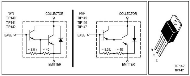
This is an economical 150 Watt amplifier circuit featuring two Darlington power transistors, TIP 142 and TIP 147. The circuit is capable of delivering up to 150 W RMS to a 4 Ohm speaker, providing substantial audio output. The...
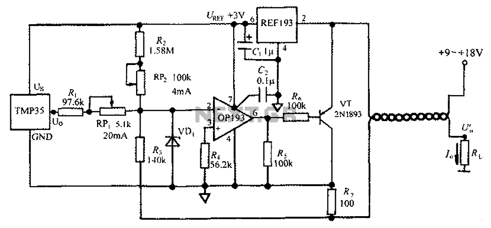
The circuit consists of a TMP35 temperature transmitter that converts a voltage signal output from the TMP35 into a standard 4 to 20 mA current signal. This configuration is suitable for use in automated instrumentation and industrial temperature control...
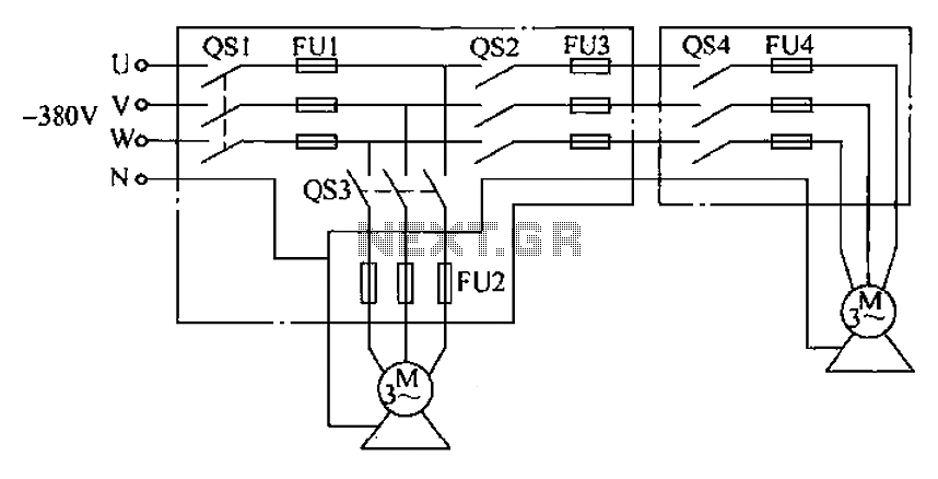
The agriculture and electrical power harrow plow power cord must consist of four rubber cables, with one core wire designated as the ground wire. The traction machine housing must be properly grounded. The two traction power machines are connected...
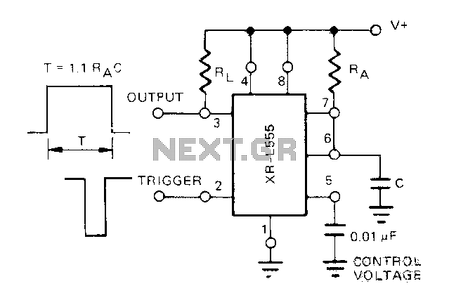
The Exars XR-L555 circuit has a typical power consumption of 900 W and operates with a power supply voltage of 5V. It is a micro-power circuit that can be used as a direct replacement for the standard 555 timer....

This board layout was created using the SOIC version of a PIC16F627A without drawing the usual schematic first. Most of the part values are etched on the Layout. The SIP resistor packs I used are 10k ohm, some experimentation...