
Micropower monostable circuit diagram

The Exars XR-L555 is a versatile timer circuit designed for low-power applications. With a power consumption of 900 W, it is optimized for efficiency, making it suitable for battery-operated devices. The circuit operates at a supply voltage of 5V, allowing it to be integrated into various electronic systems that require a reliable timing mechanism.
The XR-L555 functions similarly to the classic 555 timer, providing the same timing capabilities with enhanced performance characteristics. The timing interval is adjustable through the selection of an external resistor (RA) and capacitor (C). The relationship between these components is defined by the formula:
\[ T = 1.1 \times RA \times C \]
where \( T \) is the output pulse duration. By varying the values of RA and C, users can precisely control the timing behavior of the circuit, making it suitable for applications such as pulse width modulation, timer delays, and oscillators.
In addition to its basic timing functions, the XR-L555 may also include features such as a low-power sleep mode, which further enhances its efficiency in power-sensitive applications. The micro-power design ensures that the circuit consumes minimal energy during operation, making it an ideal choice for portable and battery-operated devices.
Overall, the Exars XR-L555 circuit combines the familiar functionality of the traditional 555 timer with modern enhancements that cater to low-power requirements, providing a reliable and flexible solution for a wide range of electronic timing applications.Exars XR-L555 circuit typical power consumption is 900 W, the power supply voltage of 5V, micro-power circuit, XR-L555 can be used directly in place of the 555 timer. Delay by an external resistor and a capacitor (RA and C) control, delay determines the duration of the output pulse.
Related Circuits
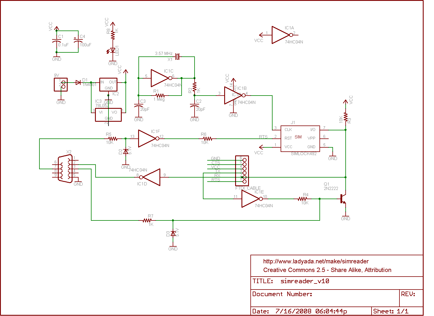
The circuit for a SIM card reader is presented here. It utilizes a CMOS hex inverter along with other basic components. Not only does it function effectively, but it is also capable of communicating with a PC through a...

The adjustable voltage monitor can be used to check whether the voltage in a circuit remains within a given range. If the DC voltage is less than the voltage at pin 5 of U1-B, then LED1 will light. If...
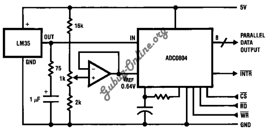
This is a design for a temperature-to-digital converter circuit that is controlled by the LM35 integrated circuit. The LM35 is a precision integrated circuit temperature sensor, whose output voltage is linearly proportional to the Celsius temperature. The circuit utilizes the...
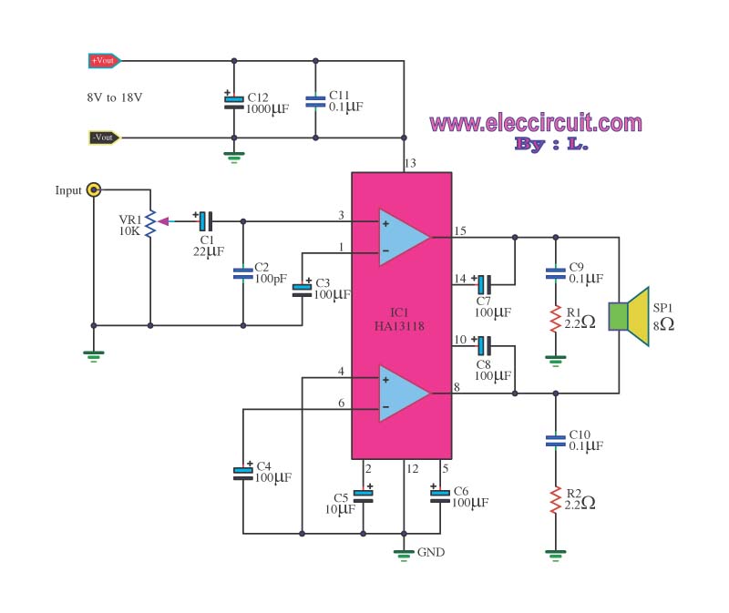
The amplifier circuit utilizes the HA13118 IC, a Hitachi component designed to deliver 18 watts of output power. This integrated circuit operates as a Class AB amplifier. The HA13118 IC is a versatile audio amplifier designed for high-fidelity applications, providing...
The following circuit illustrates a curtain control circuit diagram. This circuit is based on the 555 integrated circuit (IC). Features include a switch for manual control, the IC, and additional components. The curtain control circuit utilizes the 555 timer IC...
This circuit is a wireless car alarm system constructed using two modules: a transmitter module and a receiver module. It operates on FM radio waves and is suitable for vehicles with a power supply of 6-12VDC. A voltage stabilizer...