
How To Build A Simple Keypad Switch With A Tamper Alarm

The circuit operates by integrating several components to ensure effective tamper protection and user feedback through auditory signals. The CMOS 4017 decade counter is pivotal in counting the number of incorrect key presses, providing a straightforward method for determining when to activate the alarm system. The alarm system is designed to deter unauthorized access while allowing legitimate users to reset the system without complete deactivation.
The use of a relay connected to the buzzer output enables the option to integrate a more powerful alarm system, such as a siren, enhancing the deterrent effect. The choice of C3 and R3 values is critical, as these components dictate the time delay for keypad reactivation post-lockout, allowing for a balance between security and user convenience.
The inclusion of control switches Sw1 and Sw2 provides flexibility in managing the alarm system. Sw1's function to silence the alarm without unlocking the keypad allows users to manage false alarms effectively, while Sw2's ability to reset the system quickly is crucial in emergency situations. The design also accommodates the use of a magnetic reed switch for stealthy operation, which can be particularly useful in applications requiring discreet security measures.
Connections between the Tamper-Alarm and Keypad Circuit are straightforward, ensuring ease of integration into existing systems. The logic behind the counting mechanism is robust, allowing for a clear distinction between valid and invalid key presses, thereby enhancing the overall security of the system. This circuit design effectively combines functionality and security, making it suitable for various applications requiring keypad access control.This circuit is designed to be used with the Universal Keypad Operated Switch. A few genuine mistakes - made during code entry - will not activate the device. But repeated attempts to find the correct code by trial and error - will cause the keypad to lock-up - and the Buzzer to sound. Connect the coil of a suitable relay to the Buzzer output - a nd you can sound a Siren instead. The circuit uses a Cmos 4017 decade counter. It counts the number of times a "Wrong" key is pressed. When the count reaches eight - it sounds the alarm and locks the keypad. The alarm will continue to sound - and the keypad will remain locked - for a period of time set by the values of C3 and R3. With the values shown - this takes about five minutes. Then the keypad becomes active once more - and the alarm is silenced. Two different control switches are provided. The first - Sw1 - simply stops the noise. Removing the lock from the keypad is left to the timer circuit. Sw1 gives you the option to silence the alarm - and still retain the keypad protection. Sw2 shortens the time it takes for C3 to charge. It both removes the lock from the keypad - and stops the noise. Any small normally-open switch will do. If you use a magnetic reed-switch - you can hide the switch within the keypad housing - and use a magnet to reset the alarm.
There are three connections to be made between the Tamper-Alarm and the Keypad Circuit. Connect "Com" on the Tamper-Alarm Circuit to "Com" on the Keypad Circuit. Connect "X" on the Tamper-Alarm Circuit to Pin 1 of the 4081. And connect "Y" on the Tamper-Alarm Circuit to the junction of the relay coil and the collector of Q6. The count advances by one every time a "Wrong" key is pressed. A wrong key is any key that takes pin 1 of the 4081 low. Since "E" takes pin 1 low - "E" is a wrong key. Therefore - when you press "E" to energize the relay - the count will always advance to one. That leaves seven more wrong-key inputs before the Tamper-Alarm will activate. Note that "A" and "B" never take pin 1 low - so pressing them does not advance the count. 🔗 External reference
Related Circuits
This is the lowest cost dialing alarm on the market and shows what can be done with an 8-pin microcontroller. The complete circuit is shown below. You cannot see all the features of this project by looking at the...

This circuit allows multiple cameras to be connected to a single monitor. It can be operated either manually or automatically. In automatic mode, a switch is connected to the output of a 555 astable multivibrator, which generates a continuous...

The transmitter part of the circuit is built around IC1 (NE 555), which is configured as an astable multivibrator operating at 40 kHz. The output from IC1 is amplified by a complementary pair of transistors (Q1 and Q2) and...

When this car alarm circuit is activated, it remains active for 80 seconds. There is a 15-second delay for the driver to enter and deactivate the alarm. All timings can be easily modified. The circuit utilizes two NE555 timers,...
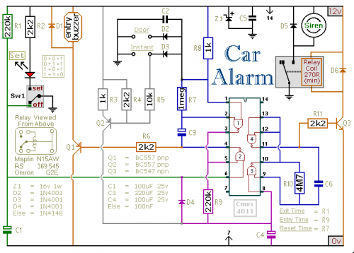
This car alarm circuit includes Exit and Entry delays, an instant alarm zone, an intermittent siren output, and an automatic reset function. By incorporating external relays, it is possible to immobilize the vehicle and activate the lights. The car alarm...

This is an automatic emergency lamp equipped with daylight sensing capabilities, enabling it to detect darkness and automatically turn on. Conversely, it senses daylight and turns off automatically. This straightforward emergency lamp does not require any special equipment, not...