
Ultrasonic switch

The circuit described operates on principles of ultrasonic transmission and reception, utilizing a combination of analog and digital components to achieve its functionality. The NE 555 timer IC, configured in astable mode, generates a continuous square wave signal at a frequency of 40 kHz, which is characteristic of ultrasonic applications. This frequency is chosen to ensure effective transmission and detection of ultrasonic waves.
The complementary transistor pair (Q1 and Q2) serves to amplify the output signal from the NE 555 timer, allowing for sufficient power to drive the ultrasonic transmitter (K1). The push-button switch (S1) provides a simple user interface for activating the transmitter, enabling the system to be turned on and off as needed.
The receiver section employs an ultrasonic transducer (K2) that is sensitive to the frequency of the transmitted signal. Upon receiving an ultrasonic wave, the transducer converts the mechanical wave into an electrical signal, which is typically weak and requires amplification. The two-stage amplifier, composed of transistors Q3 and Q4, enhances this signal to a usable level.
The diodes (D3 and D4) are critical in the rectification process, converting the amplified AC signal into a DC signal suitable for further processing. The operational amplifier, configured as a comparator, compares the rectified signal against a reference voltage. This comparison allows for the detection of the presence of ultrasonic signals. When an ultrasonic signal is detected, the output of the comparator transitions, triggering the subsequent transistors (Q5 and Q6) that drive the relay.
The relay serves as a switch to control larger loads, effectively isolating the low-power circuit from the high-power load. The inclusion of diode D5 as a freewheeling diode is essential for protecting the circuit from back EMF generated by the relay coil when it is de-energized, ensuring longevity and reliability of the components involved. Overall, this circuit design exemplifies a practical application of electronic components in ultrasonic sensing and control systems.The transmitter part of the circuit is build around IC1(NE 555). The IC1 is wired as an astable multi vibrator operating at 40KHz. The output of IC1 is amplifier the complementary pair of transistors ( Q1 & Q2) and transmitted by the ultrasonic transmitter K1. The push button switch S1 is used the activate the transmitter. The receiver uses an ultras onic sensor transducer (K2) to sense the ultrasonic signals. When an ultrasonic signal is falling on the sensor, it produces a proportional voltage signal at its output. This weak signal is amplified by the two stage amplifier circuit comprising of transistors Q3 and Q4.
The output of the amplifier is rectified by the diodes D3 & D4. The rectified signal is given to the inverting input of the opamp which is wired as a comparator. When ever there is an ultrasonic signal falling on the receiver, the output of the comparator activates the transistors Q5 & Q6 to drive the relay. In this way the load connected via the relay can be switched. The diode D5 is used as a free wheeling diode. 🔗 External reference
Related Circuits
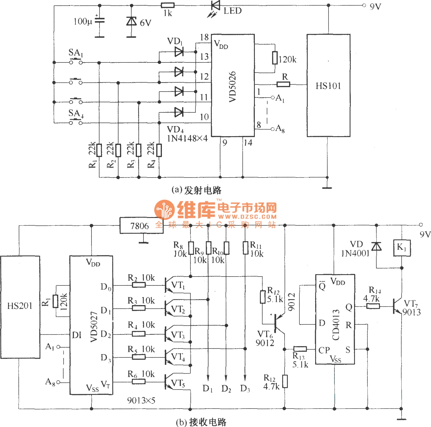
HS101 and HS201 are small radio transceiver components operating at a frequency of 280 MHz, designed for digital signal transmission. They provide a control distance ranging from 30 to 100 meters. All components, including the antenna, are integrated into...
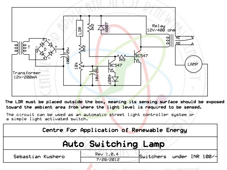
The light-activated switch circuit can be used for switching off a particular lamp or group of lamps in response to varying ambient light levels. The light-activated switch circuit utilizes a light-dependent resistor (LDR) as the primary sensing element to detect...

This circuit generates inaudible ultrasound to create a barrier across an entry point. When the circuit detects a disruption in the sound barrier, it triggers a loud alarm to indicate the entry of a person. This system can be...
A 100 second delayed turn ON relay RL1 switch, if plug power +12V in circuit. In Fig.2 see a two range 6-60 second and 1-10 minute auto turn off relay timer circuit, with 555. Part List R1=1 Mohms C4=100nF...
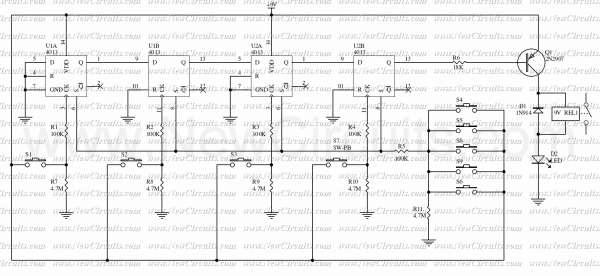
This circuit is very basic to build. To open a lock which is connected to the K1 Load, you must press each momentary switch in the correct sequence. The sequence used in this circuit is S1, S2, S3 and...
The reset switch on a computer is crucial. If an operating instruction threatens to disrupt the internal management of a computer, the reset button is often the only way to prevent a potential disaster. However, it can also lead...