
Simple Emergency Light
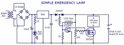
The automatic emergency lamp circuit is designed to provide reliable lighting during power outages or low-light conditions. The core functionality relies on the LDR, which detects ambient light levels. When the light level drops below a certain threshold, the LDR's resistance increases, triggering the circuit to activate the LEDs. Conversely, when the light level rises above the threshold, the LDR's resistance decreases, causing the circuit to deactivate the LEDs.
The 3-pin fixed voltage regulator is crucial for maintaining a stable voltage output, ensuring that the LEDs operate efficiently without risk of damage from overvoltage. The built-in current limiting feature protects the circuit from excessive current draw, which is particularly important when dealing with rechargeable batteries. The design allows for the use of standard components, making it accessible for hobbyists and those with limited resources.
The choice to connect two LEDs in series is a strategic decision that enhances energy efficiency. By using two LEDs, the circuit can achieve greater brightness without requiring additional current, thus prolonging battery life. The absence of a dropping resistor simplifies the design and reduces component count, making it easier to assemble.
The housing of the circuit in a repurposed emergency lamp not only promotes sustainability but also provides a practical application for the design. The prototype photographs and PCB design included with the documentation serve as valuable references for builders, offering visual guidance for assembly and layout. Overall, this automatic emergency lamp circuit exemplifies a user-friendly approach to creating an efficient lighting solution.This is an automatic emergency lamp with day light sensing, means it senses darkness/night and turns ON automatically. Similarly it senses day light and turns OFF automatically. A simple emergency lamp which does not require any special equipment; even a multimeter to assemble and use.
Any individual who can do a good quality soldering must be abl e to build this circuit successfully. This can be easily accommodated in the defunct two 6 watt tube National Emergency Lamp or any PL tube type emergency lamp. The difference will be in the working; it will work non stop for more than 8 hours. Deep discharge is taken care by the LED characteristic and over charge protection is taken care by the fixed voltage regulator.
This uses a simple 3Pin fixed regulator which has a built in current limiting circuit. The only required adjustment is the preset which has to be set to ensure the LEDs just light up (it should be left at that position). The 5mm LDR is just mounted on top of the emergency light as shown in the photograph. LDR is used to avoid it lighting up during day time or when the room lights are ON. 2 LEDs are used in series; the dropping resistance is avoided and 2 LEDs light up with current that is required for a single LED, by which energy is saved to a great extent.
This particular circuit has been kept so simple for people who has limited access to components or in other words this is an emergency light that you can build with minimum components. In addition to circuit diagram, He has shared photographs of the prototype he made in National emergency light and a PCB design.
🔗 External reference
Related Circuits
is circuit was requested from an email. It will allow your car headlights to flash on and off at the same time or it will cause them to flash alternately. The circuit is based on the 555 timer. It...
Install the PIR module hanging from a 3-meter high mast to cover a 10-meter radius area. Connect its supply and relay terminals to the finished and enclosed circuit, ensuring the correct polarity is observed. A 4-core screened cable can...

The drawing below illustrates a multistage light sequencer using discrete parts and no integrated circuits. The idea is not new and I hear a similar circuit was developed about 40 years ago using germanium transistors. The idea is to...
Streetwear trench pipe installation commonly utilizes concealed wiring methods. The control section is installed at the front door or in a centralized control room, managed by a duty electrician. The street factory area is illustrated in a figure. This...
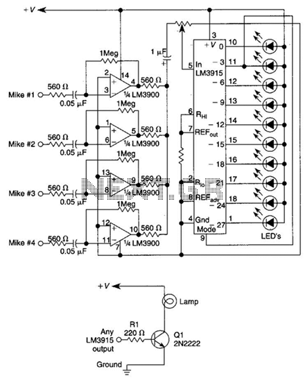
This circuit will produce an output when the sound exceeds a preset level. The LM3915 is a log-output bar graph driver. A transistor driver is used for higher current loads. To drive heavy-current loads with an LM3915 output, a...
This is a range of IF signal circuits that may be of interest to radio hobbyists and professionals alike. Transistors T1 and T2 form an astable multivibrator oscillating in the audio frequency range of 1 to 2 kHz. An...
Warning: include(partials/cookie-banner.php): Failed to open stream: Permission denied in /var/www/html/nextgr/view-circuit.php on line 713
Warning: include(): Failed opening 'partials/cookie-banner.php' for inclusion (include_path='.:/usr/share/php') in /var/www/html/nextgr/view-circuit.php on line 713