
Connection Testers

The circuit operates by leveraging the differential input characteristics of the 741 op-amp, which is designed to amplify the voltage difference between its two inputs. When the probes are connected to a resistor, the op-amp can detect minute variations in resistance due to its high input impedance. The 470kΩ and 10kΩ resistors serve to introduce a controlled imbalance, enabling the op-amp to react to small changes in resistance effectively.
In practical applications, the continuity tester can be used to verify electrical connections in a variety of components, ensuring that circuits are complete and functional. The adjustment of the control resistor allows the user to calibrate the sensitivity of the circuit, accommodating different ranges of resistance values.
To ensure reliable operation, the probes should be kept clean to minimize contact resistance, which could otherwise lead to erroneous readings. The circuit's versatility is enhanced by its compatibility with various op-amp types, allowing for customization based on specific application needs. The use of a preset resistor for offset nulling further improves the circuit's accuracy, ensuring that the LEDs only illuminate under the desired conditions.
Overall, this continuity tester provides a simple yet effective solution for checking electrical connections, with the potential for adaptation to various op-amp configurations to suit different testing scenarios.This simple circuit uses a 741 op-amp in differential mode as a continuity tester. The voltage difference between the non-inverting and inverting inputs is amplified by the full open loop gain of the op-amp. Ignore the 470k and the 10k control for the moment, and look at the input of the op-amp. If the resistors were perfectly matched, then the vo ltage difference would be zero and output zero. However the use of the 470k and 10k control allows a small potential difference to be applied across the op-amp inputs and upset the balance of the circuit. This is amplified causing the op-amp output to swing to full supply voltage and light the LED`s. The probes should first be connected to a resistor of value between 0. 22 ohm and 4ohm. The control is adjusted until the LED`s just light with the resistance across the probes. The resistor should then be removed and probes short circuited, the LED`s should go out. As the low resistance value is extremely low, it is important that the probes, (whether crocodile clips or needles etc) be kept clean, otherwise dirt can increase contact resistance and cause the circuit to mis-operate.
The circuit should also work with a MOSFET type op-amp such as CA3130, CA3140, and JFET types, e. g. LF351. If the lED`s will not extinguish then a 10k preset should be wired across the offset null terminals, pins 1 and 5, the wiper of the control being connected to the negative battery terminal. A pin out for the 741 can also be found on my practical section. 🔗 External reference
Related Circuits
This simple circuit is designed to test transistors in a circuit, capable of measuring down to 40 ohms across the collector-base or base-emitter junctions. It is also suitable for checking output power transistors in amplifier circuits. The operation of...
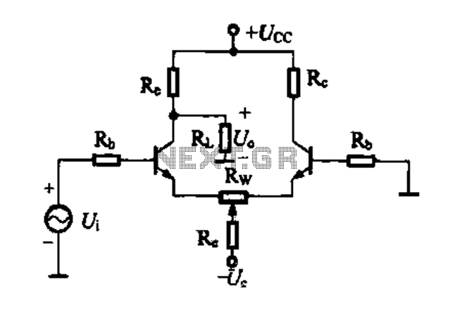
A differential amplifier circuit can be connected in four different ways, allowing for a comparison of their characteristics. The gain of the amplifier is equivalent to that of a single tube, with half the gain providing a high common-mode...
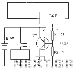
The circuit operation principle of the device illustrated in Figure 13 is as follows: When the barbed wire (Fe) remains intact, the output pin (O) of the LSE is at a high state. Consequently, the transistor (VT) remains off,...
This is a simple crystal tester circuit. The transistor T1 and the crystal form an oscillator. Capacitors C1 and C2 act as a voltage divider for the oscillator. If the crystal is functioning properly, the oscillator will operate effectively,...
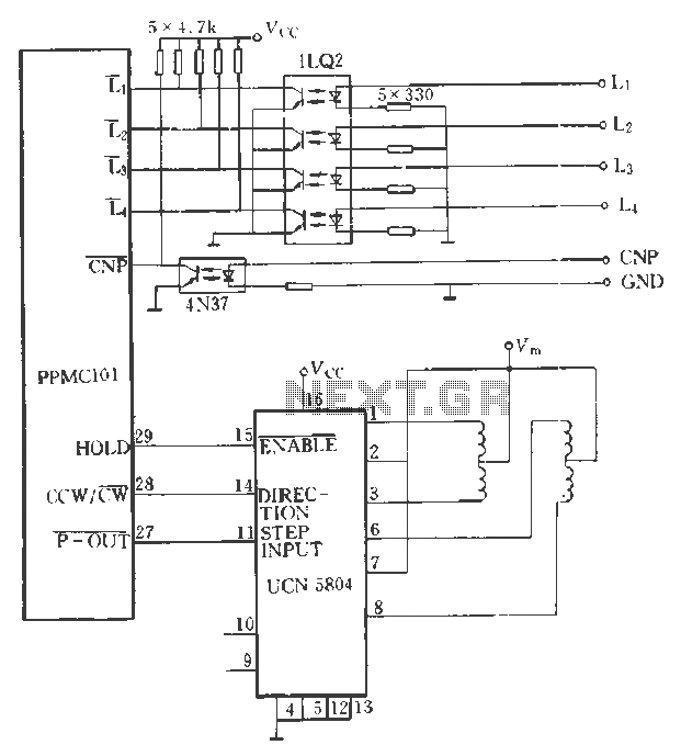
The PPMC external UChl 5804 demonstrates a four-phase stepping motor drive integrated circuit (IC) that is depicted in a downward motion. It utilizes the P-OUT, counterclockwise (ccw) / clockwise (cw), and HOLD outputs. The UCN5804 pins 9 and 10...
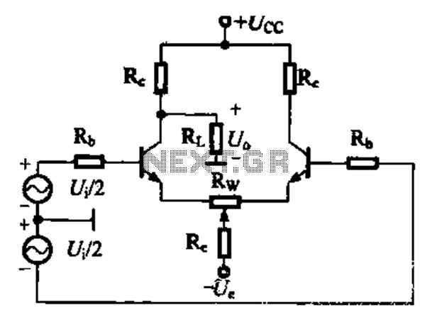
A comparison of four connection methods and features of a differential amplifier circuit is presented. The circuit demonstrates a magnification of a single tube with half the earnings, effectively countering common-mode negative feedback effects. The Common-Mode Rejection Ratio (CMRR)...