
Allowing only one-way operation of the motor-controlled circuit 2
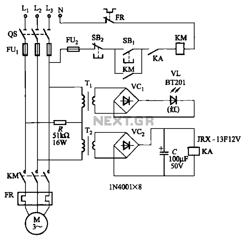
The circuit functions as a protective mechanism for three-phase motors, ensuring that the motor operates only under correct phase conditions. The dual-phase sequence protection relay monitors the incoming phase sequence and activates the relay KA only when the sequence is correct. If any phase is out of order, KA will release, which interrupts the operation of contact KM, thus preventing potential damage to the motor due to incorrect phase conditions.
The use of transformers T1 and T2 with specified turns ratios is crucial for stepping down the voltage levels to manageable values for the relay and other components. The 100:1 ratio for T1 allows for significant voltage reduction, making it suitable for the relay's operating voltage requirements. Similarly, T2 with a 100:3 ratio serves to further adjust the voltage for additional circuit components, ensuring that all elements operate within their rated limits.
The alarm system integrated into the circuit is indicated by diode VL, which provides visual feedback when the relay KA is activated. This feature is essential for operators to quickly assess the operational status of the motor and the phase sequence. The overall design of the circuit prioritizes safety and reliability, ensuring that the motor remains protected against phase sequence faults, which can lead to overheating, mechanical failure, or other electrical hazards.
In summary, the circuit represented in Figure 3-92 is a sophisticated solution for phase sequence protection in three-phase systems, utilizing relays and transformers to maintain operational integrity and provide alerts for any anomalies. Circuit shown in Figure 3-92. It uses dual-phase sequence protection relay sense. When the power positive phase sequence (U, V, w), following the electrical KA pull. If the pow er supply phase sequence right, KA release, contact KM can not pull the motor does not work. Same time emitting diode VL light alarm. FIG transformer Ti, Tz becomes ratios of 100: 1 and 100: 3. A rated voltage of 380V, capacity is the number of VA.
Related Circuits
This is the large controller utilized for the game Steel Battalion for the Xbox. The schematic diagram was sourced from an individual named Alpha who created it for his own use. The Steel Battalion controller is a specialized input device...
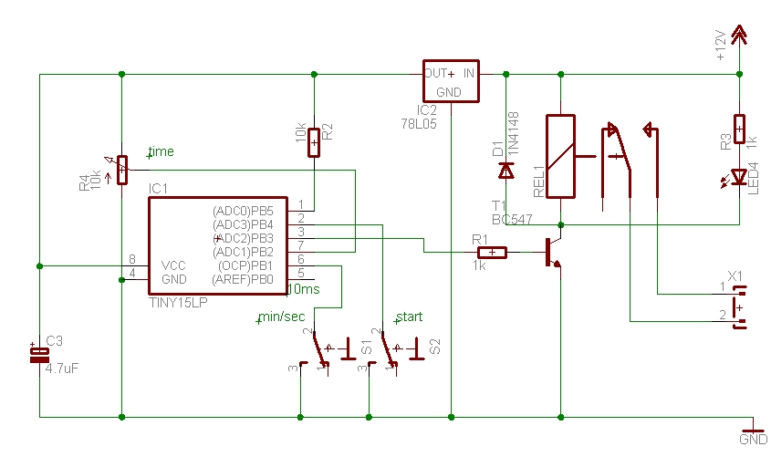
The time can be set using a potentiometer ranging from 1 minute to 1023 minutes, approximately 17 hours. A pushbutton initiates the timing process, activates a relay, and the timer will deactivate the relay once the set time has...
The ZN414 integrated circuit (IC) contains a complete automatic gain controlled AM receiver within a compact three-pin package. With only a few external components, it is possible to construct a simple radio that offers excellent selection and reception capabilities....
This simple flashing light circuit operates at 6 volts and 0.5A, exhibiting low current consumption when the light bulb is turned off. The frequency of the flashing is predetermined. The circuit consists of a power supply, typically a battery or...
Most of the power supply failure indicator circuits need a separate power supply for themselves. But the alarm circuit presented here needs no additional supply source. It employs an electrolytic capacitor to store adequate charge, to feed power to...
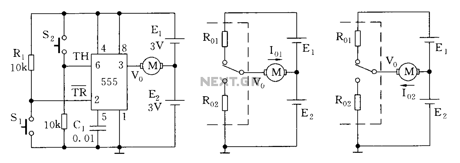
The 555 timer in bistable mode has fewer applications compared to its stable and monostable modes. Bistable mode refers to the circuit configuration based on the R-S (Reset-Set) trigger mode. An example of this is a micro-motor reversing control...