
how to make 18 led light chaser circuit
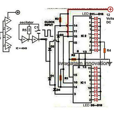
The 18 LED light chaser circuit begins with the clock signal generated by the IC 4049, which is a hex inverting buffer. This IC provides the necessary timing pulses that drive the counting operation of the two cascaded 4017 decade counters. Each 4017 IC has ten outputs, and by cascading two of them, the total number of outputs available for driving LEDs increases to twenty, although only eighteen LEDs will be utilized in this application.
In this configuration, the outputs of the first 4017 are connected to the inputs of the second 4017 through diodes. These diodes ensure that when an output goes high on the first IC, it triggers the corresponding input on the second IC, allowing the light chasing effect to continue seamlessly. The LEDs are connected to the outputs of both ICs, with the first ten LEDs connected to the outputs of the first IC and the additional eight connected to the outputs of the second IC.
To construct the circuit, the following components are required: two 4017 decade counter ICs, one 4049 inverter IC, eighteen LEDs of desired colors, resistors to limit the current through the LEDs, and a few diodes for cascading the outputs. The resistors are typically chosen to be around 220Ω to 1kΩ, depending on the forward voltage of the LEDs being used. The circuit can be powered using a 9V battery or a suitable DC power supply, ensuring that the voltage levels are within the operating range of the ICs.
This simple yet effective circuit not only provides an engaging visual display but also serves as an excellent introduction to the concepts of digital electronics, including counting, cascading, and the use of basic logic components. By experimenting with different configurations of LEDs and modifying the clock frequency, users can further enhance the effects produced by this light chaser circuit.Decorative lights arranged in different moving patterns look very interesting and are surely eye catching and that`s why these types of lighting arrangement have gained immense popularity in today`s world. Though the more complex lighting might need the incorporation of microcontroller ICs, simpler yet very interesting light effects can be generat
ed through ordinary ICs, which require very few components for the configuration. A light chaser circuit is a configuration which generates a running or chasing light pattern which goes on repeating itself from start to finish, producing a very eye catching and fascinating light pattern. Here we are discussing how to make a simple 18 LED light chaser circuit which can be built by any newcomer in the field albeit the individual has some knowledge of soldering and regarding the commonly used electronic components.
The circuit of a light chaser discussed here utilizes the popular Johnson`s decade counter IC 4017 for getting the desired light chasing effect. Another IC 4049 provides the clock signals to the counter ICs. We all have probably seen how the IC 4017 can be configured for creating the light chasing effect using LEDs, however the number of maximum LEDs supported by this IC is not more than ten.
In this article we`ll learn how to make an eighteen LED light chaser by cascading two of these ICs. Looking at the figure we see how the two ICs are configured so that the chasing of the LEDs at its outputs are carried on for 18 LEDs. The diodes included in the circuit especially are responsible for switching the ICs into a cascading action.
The diodes make sure the IC outputs are carried forward from one IC to another, so that the chasing effect is pulled for the entire 18 LEDs in the array. 🔗 External reference
Related Circuits
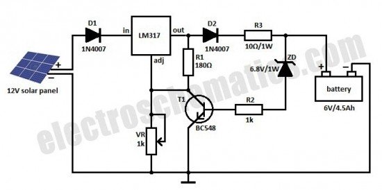
This is a solar charger circuit designed to charge Lead Acid or Ni-Cd batteries using solar energy. The circuit captures solar energy to charge the batteries. The solar charger circuit typically consists of several key components, including a solar panel,...
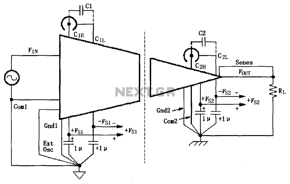
The basic connection circuit for ISO120/121 includes signals and power supply. Each power supply terminal must have a 1 µF tantalum capacitor as a bypass filter, and the printed circuit board layout should allow for the bypass capacitor to...
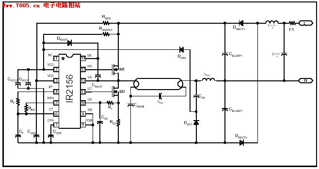
The IR2156 provides a cost-effective solution for fluorescent electronic ballasts. It integrates features such as lighting tube error protection and a programmable working frequency, which includes warm-up, lighting, and continuous operation of the ballast. The IR2156 is a highly integrated...
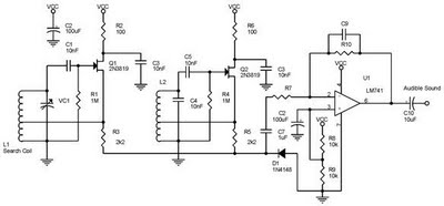
One type of metal detector is a beat frequency oscillator (BFO). The operation of metal detectors relies on changing the characteristics of the oscillator when it is near a metal object detected by the sensor. The detector functions based...

This temperature meter utilizes the precision micro power centigrade sensor IC LM35. The output voltage of the IC is linearly proportional to 10 mV per degree centigrade. The LM35 temperature sensor is a versatile and widely used device in electronic...
This is a simple LED circuit that takes power from the USB port. I needed this USB light since long time ago but, finally, I was able to build it. The circuit schematic is so simple: Just one resistor...
Warning: include(partials/cookie-banner.php): Failed to open stream: Permission denied in /var/www/html/nextgr/view-circuit.php on line 713
Warning: include(): Failed opening 'partials/cookie-banner.php' for inclusion (include_path='.:/usr/share/php') in /var/www/html/nextgr/view-circuit.php on line 713