
How to make a JDM Programmer

The JDM programmer serves as a fundamental tool for microcontroller programming, particularly for users engaging in their first projects. Its reliance on the RS232 DB9 interface ensures compatibility with many legacy systems, while its simplicity and low cost make it accessible for educational and hobbyist purposes. The use of WinPIC800 software enhances the programmer's functionality, allowing for efficient code loading into the microcontroller. The design includes essential components, such as the 40-pin base, which facilitates easy access to the microcontroller for programming and debugging.
The schematics provided, both original and modified, are crucial for guiding users through the assembly process. The original schematic accommodates various microcontrollers, while the modified version streamlines the design specifically for the PIC18F4550, eliminating unnecessary components and simplifying the build process. The emphasis on using a desktop computer is important, given the incompatibility of many laptops with the required serial connections. The active pins on the connectors are clearly defined, ensuring correct wiring and functionality. The inclusion of a resistor between RS232-8 and RS232-4 is a key detail that aids in signal integrity.
Overall, this JDM programmer represents a valuable resource for those looking to delve into microcontroller programming, providing a practical and cost-effective solution for learning and experimentation. The guidance on component selection and schematic adherence will help users achieve successful programming outcomes.This JDM programmer works with a RS232, 9-pin(9 wire) DB9 Serial connector on your computer, and is used for loading Source Code (hex files) into your microcontroller. JDM programmers are Cheap and very easy to make. JDM programmer that we are going to make will be used for loading the code into microcontroller board.
You can probably buy this JDM Online or from some Electronic store but if you are going to make one for yourself then, total spending for all components and board will cost you less than half of the actual price of the JDM that you will get in any electronic store. This jdm programmer responds, or lets us to burn the program into the microcontroller chip through small software known as winpic800.
Winpic800 is compatible with pic18f4550 and JDM serial programmer. It works with lot of other hardware too, which are similar to JDM programmer, like the [GTP-USB] but it costs around 60 ‚¬ from their official website. So it`s a good option for beginners to stay with JDM programmer as cheap alternative in the early stages.
Later for a better programmer I recommended pickit3 from microchip which makes it easier to program with a USB port. As of now with this JDM programmer we are going to program PIC18F4550 USB Interface Board for FIRST TIME BURNING OF CODE INTO THE CHIP This JDM programmer uses RS232 DB9 port to program the code into the microcontroller.
I recommend do not use a laptop for JDM programmer. Usually now a days laptop`s does not comes with a DB9 serial port, so if you are thinking to use a USB to DB9 converter cable for doing this job then its a bad idea. Don`t even think about USB to DB9 converter, it just won`t work. So I recommend use a Desktop Computer which comes with an inbuilt DB9 Serial port. If you are thinking of a USB programmer then pickit2 or pickit3 will be a good option. I found a nice tutorial about long time ago for making this JDM programmer. The name of the device was JDM EXTREME. I don`t remember where I found it, but I still have Schematic for making it. I have modified the actual schematic according to our need for this programming 40 pin microcontroller.
I have posted both the actual Schematic and modified Schematic below. FOLLOW THE SECOND SCHEMATIC FOR 40PIN Microcontroller board. The 1st one is actual schematic which can be used for verities of JDM supported microcontrollers (you can modify it according to the type of microcontroller you want to use) and second one is the modified schematic (removed all non-required components for our microcontroller) which we are going to use for 1st time programming of our pic18f4550 USB interface board. While buying these components take a printout of the schematic along with you. Use a 40 pin base for holding the microcontroller; don`t solder the microcontroller into board. With a 40-pin base YOU will be able to easily chip off the microcontroller from the JDM Programmer board any time after you are done with programming.
On SV1 only pin no 1, 11 and 12 are hard active lines. And on SV2 only pin no. 1, 2, 5, 9, 11 are active. Please note that pin no 11 on SV1is actually connected with pin no. 9 on SV2 and pin no 12 on SV1 is connected to pin no 11 in SV2. RS232-8 is connected to RS232-4 with a 1. 5 k resistor. The winpic800 need to be configured with JDM Programmer according to PIC18F4550. That I am going to explain in my next post " how to configure winpic800 with a JDM programmer ". 🔗 External reference
Related Circuits
This programmer requires only a basic terminal program capable of uploading an ASCII PIC HEX file. It does not matter what operating system or computer (MAC, Win98, XP, Vista, DOS, Linux, etc.) is used to talk to it. All...
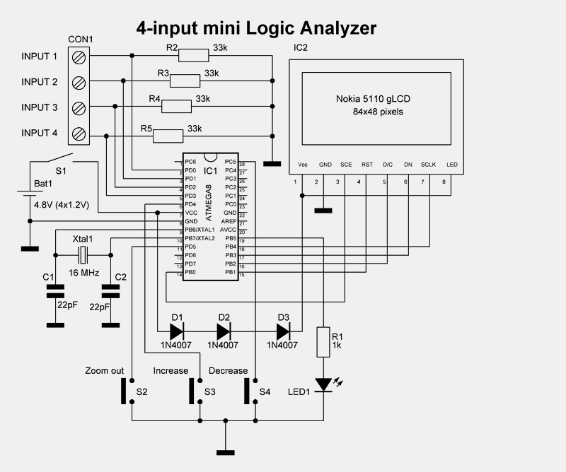
This mini logic analyzer is a tool that allows users to observe the logic transitions (0 or 1) of a digital data signal on an LCD display. Such digital data signals can be found on the output pin of...
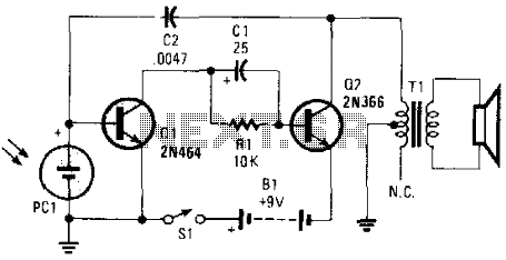
This electronic music maker utilizes an astable oscillator circuit that is regulated by a photocell. The intensity of light falling on the photocell influences the tone. By enclosing the circuit within a box, it is possible to manipulate the...
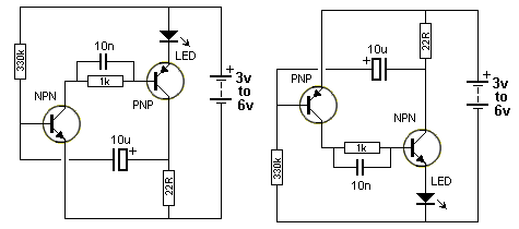
The circuit involves powering an LED using a 3V CR2032 battery, with the intention of extending battery life by making the LED blink rather than remain continuously on. A 555 timer is considered, utilizing large value resistors in the...
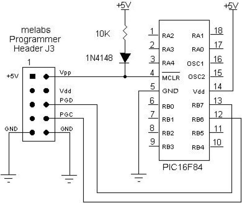
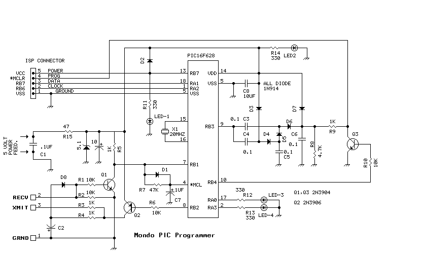
The EPIC Plus Programmer, also known as the Serial Programmer, USB Programmer, or U2 USB Programmer, can be utilized for in-circuit serial programming of serially programmable PIC Microcontrollers via the 10-pin expansion header J3. Connections for Vpp, RB6, RB7,...
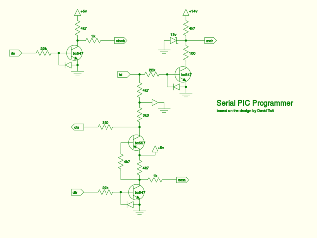
Circuit schematic for the classic PIC serial programming cable. A high-resolution version of the image and a Scalable Vector Graphics (SVG) source file for printing are also available. It is important to note that the SVG file may not...