
how to make capacitive discharge
The capacitor discharge ignition (CDI) system is a critical component in modern vehicle ignition systems, providing enhanced performance and reliability. The circuit's architecture typically includes a low-voltage input from the vehicle's battery, which serves as a baseline for operation. The alternator's high-voltage output is tapped directly, often utilizing a transformer or a specific winding designed to handle the increased voltage. The diodes in the circuit serve dual purposes: they rectify the alternating current (AC) generated by the alternator into direct current (DC) and protect the circuit from reverse voltage spikes.
The SCR plays a pivotal role in controlling the timing of the discharge from the capacitor to the ignition coil. When the SCR is triggered, it allows the stored energy in the capacitor to flow into the primary winding of the ignition coil. The magnetic field generated in the coil induces a much higher voltage in the secondary winding, which is then directed to the spark plugs. This process is crucial for achieving the rapid ignition needed for efficient engine performance.
The high-voltage capacitor is essential for storing energy quickly and releasing it in a controlled manner. Its ability to handle high voltage and discharge rapidly makes it ideal for this application. The design of the CDI system minimizes energy loss, ensuring that more power is available for ignition, which translates to better engine response and improved fuel efficiency.
In summary, the capacitor discharge ignition system represents a significant advancement over traditional ignition methods, combining solid-state technology with efficient energy management to enhance vehicle performance. The integration of various electronic components allows for precise control over the ignition timing and energy delivery, ultimately leading to more reliable engine operation.The ignition process in any vehicle becomes the heart of the entire system as without this stage the vehicle just won`t start. To initiate the process, earlier we use to have the circuit breaker unit for the required actions. Nowadays a more efficient and long lasting mechanism has been developed for the ignitions in vehicles, called the capac
itor discharge ignition system. It incorporate an electronic circuit precisely functions like the old contact breaker, but in a solid-state electronic manner. Basically as the name suggest, ignition system in vehicles refers to the process in which the fuel mixture is ignited for initiating the engine and the drive mechanisms.
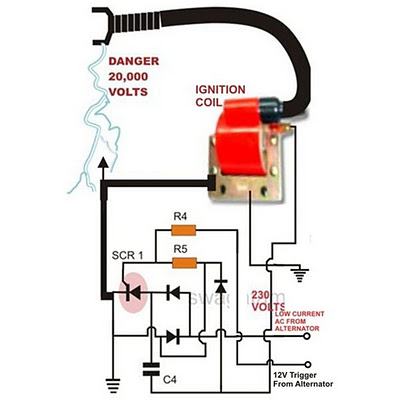
The ignition coil, which is very popular and we all have seen them in our vehicles is especially designed for the above stepping up of the input source voltage However the voltage from the alternator cannot be directly fed to the ignition coil because the source may be low in current, therefore we employ a CDI unit or a capacitive discharge unit for collecting and releasing the alternator power in succession in order to make the output compact and high with current. Referring to the above capacitor discharge ignitioncircuit diagram, we see a simple configuration consisting of a few diodes, resistors, a SCR and a single high voltage capacitor.
One source is a low voltage around 12 volts while the other input is taken from the relatively high voltage tap of the alternator, generating around a 100 volts. The 100 volts input is suitably rectified by the diodes and converted to 100 volts DC. This voltage is stored inside the high voltage capacitor instantaneously. The action generates a magnetic induction inside the coil and the input from the CDI which is high in current and voltage is further enhanced to extremely high levels at the secondary winding of the coil.
The voltage being very high in potential starts arcing across the points of the spark plug, generating the required ignition sparks for the ignition process. 🔗 External reference
Related Circuits
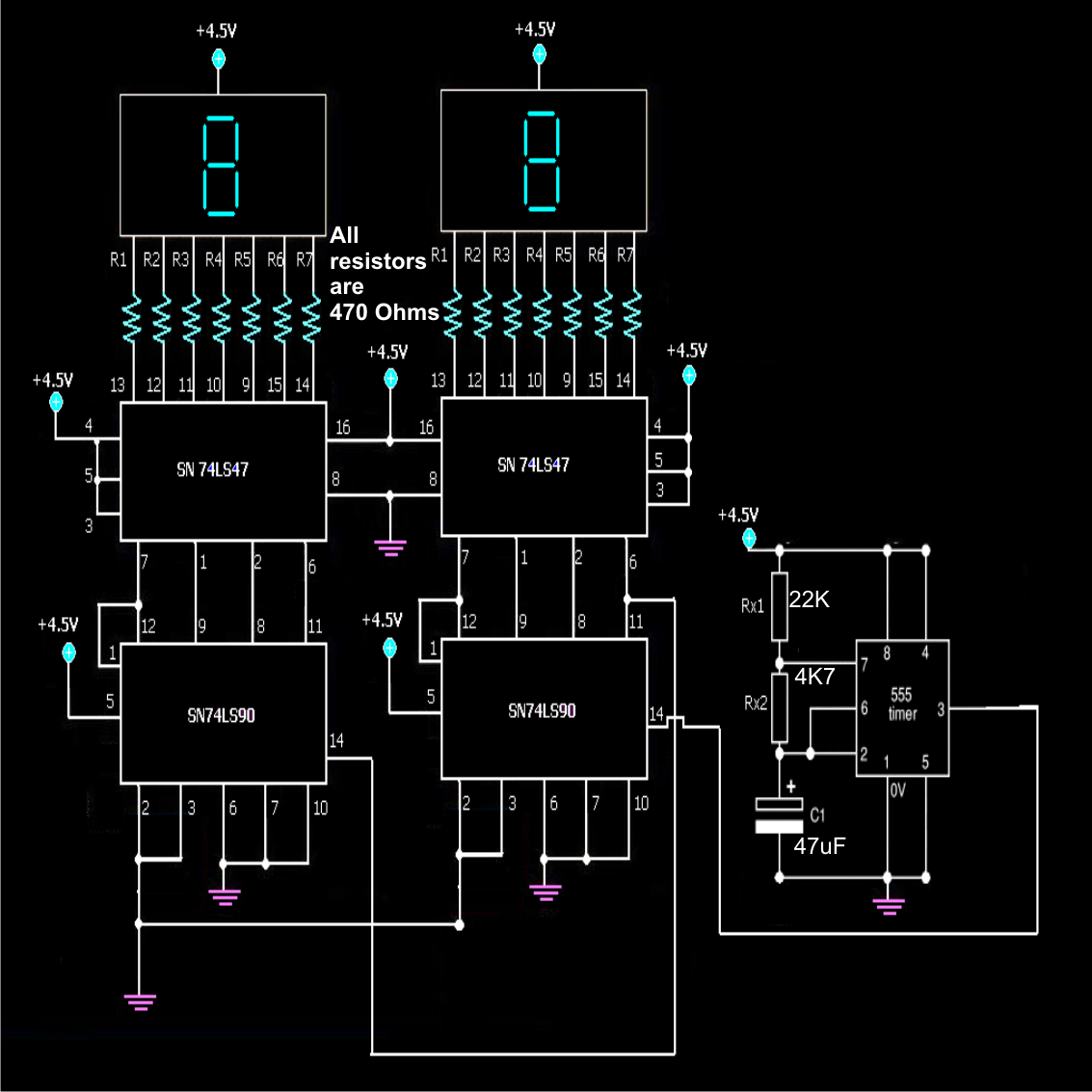
A simple frequency counter circuit can be easily constructed by any electronics enthusiast for its intended purpose. The circuit diagram was provided by Mr. Kapital through an order on Fiverr. The functioning of the circuit involves generating positive voltage...
BoardMaker3 is an integrated environment for the design of Printed circuit boards, offering a comprehensive set of tools that allow schematic entry, Spice simulation, 3D viewing and an Autorouter Interface. With a Customised graphics engine and a user configureable...
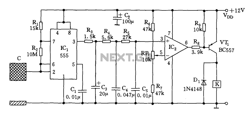
The switch circuit consists of a capacitive oscillator, an integration network, and a comparator circuit that controls a relay. When a body comes close to the induction plate, the inductive capacitance to ground increases, causing the 555 astable multivibrator...
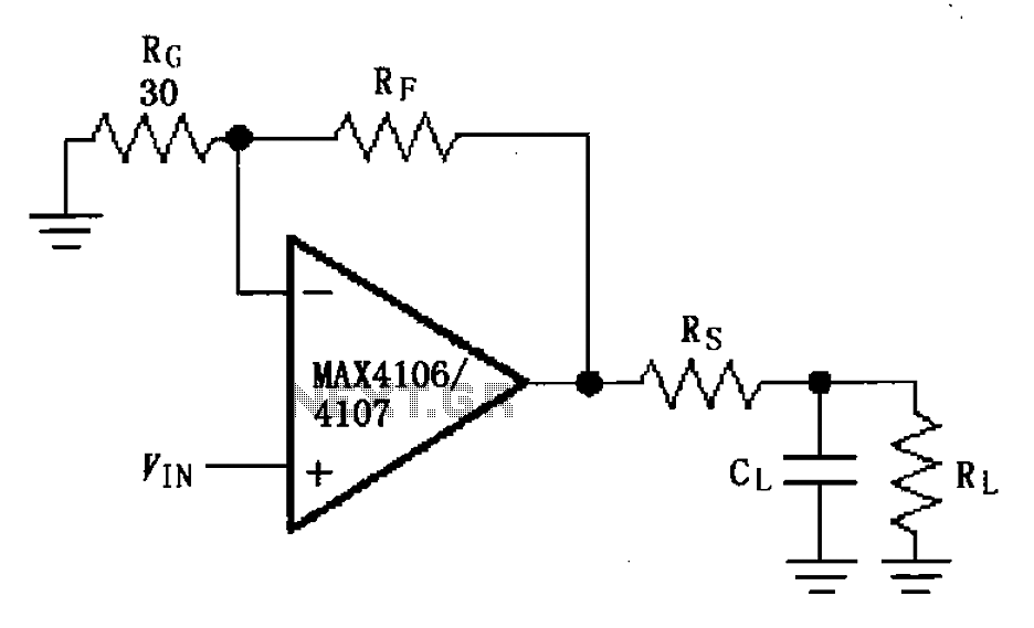
The MAX4106/4107 is designed with a capacitive load drive circuit that includes an isolation resistor (Rs). While the MAX4106/4107 exhibits excellent AC characteristics, they are not optimized for driving high reactive loads. Utilizing a high reactive load may diminish...
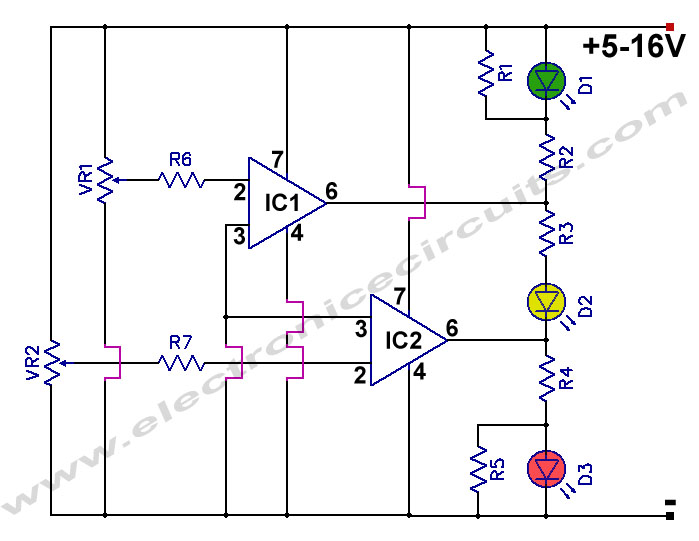
12V Battery Charge Nominal Discharge (Low) Indicator Circuit. This circuit monitors car battery voltage and provides an indication of nominal levels. The 12V Battery Charge Nominal Discharge Indicator Circuit is designed to monitor the voltage levels of a car battery...
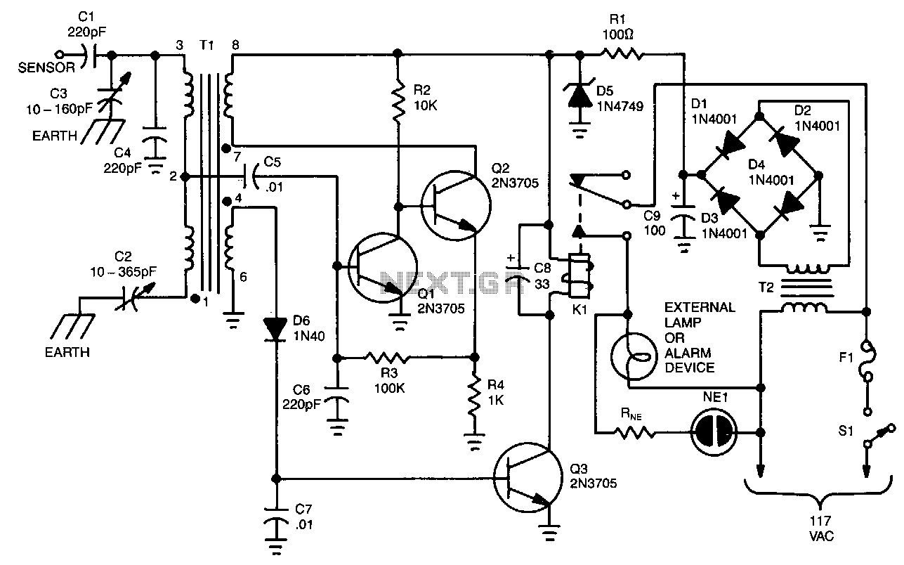
The unit is built around a balanced-bridge circuit that utilizes both capacitance and inductance. The bridge comprises capacitors C2 and C3, along with the center-tapped winding of transformer Tl. One end of the bridge is connected to ground through...