
Battery Charge Nominal Discharge Indicator Circuit
The 12V Battery Charge Nominal Discharge Indicator Circuit is designed to monitor the voltage levels of a car battery and provide a visual indication when the battery voltage drops to a nominal discharge level. This circuit typically employs a voltage divider connected to the battery terminals, which scales down the battery voltage to a level suitable for processing by a microcontroller or an operational amplifier.
The circuit may include an LED indicator that lights up when the battery voltage falls below a predetermined threshold, signaling that the battery is nearing a low charge state. The threshold can be set using a potentiometer in conjunction with the voltage divider, allowing for adjustable sensitivity based on the specific requirements of the application.
Additionally, the use of a comparator can enhance the circuit's functionality, where the output of the comparator drives the LED. The reference voltage for the comparator can be derived from a stable voltage reference or another voltage divider, ensuring that the indicator operates reliably across different battery conditions.
To protect the circuit from over-voltage conditions, a zener diode may be included in parallel with the input to clamp the voltage at a safe level for the components used. Capacitors may also be added to filter out any noise from the battery voltage, ensuring stable operation of the monitoring circuit.
Overall, this circuit serves as a vital tool for automotive applications, providing users with an early warning system to prevent battery depletion and ensuring that the vehicle remains operational.12V Battery Charge Nominal Discharge (Low) Indicator Circuit This circuit monitors car battery voltage. It provides an indication of nominal.. 🔗 External reference
Related Circuits
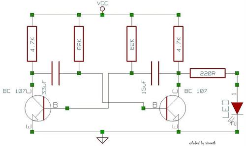
An astable multivibrator is a switching circuit that alternates its output on and off for a designated time period. This device, also known as a free-running oscillator circuit, is primarily utilized to generate square waves over a specified duration....
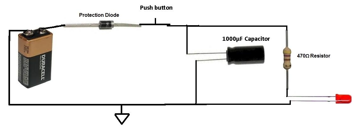
This project involves charging a capacitor with voltage, which will subsequently serve as a temporary power source for the circuit. After charging the capacitor with a battery, the battery is disconnected from the circuit. The capacitor then provides current...
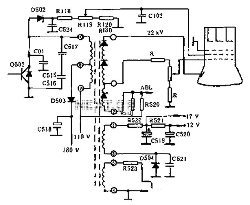
The circuit diagram of the Swallow CS37-2 type color TV illustrates the feeding tube configuration. The filament voltage is supplied by the line flyback transformer, with a current-limiting resistor R523. The accelerating voltage is managed by D502, which rectifies...
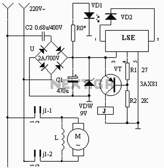
The circuit operates based on the interaction between an infrared light-emitting diode (VD1) and an infrared receiver diode (VD2). When VD1 emits infrared radiation, it is detected by VD2, which causes a decrease in its internal resistance. This change...
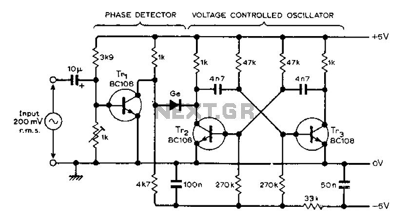
The circuit MVBR utilizes a traditional two-transistor configuration along with other components to create a simple phase-locked loop (PLL). The transistor TR1 and diodes function as a logic gate, activating during half periods of the input waveform of the...
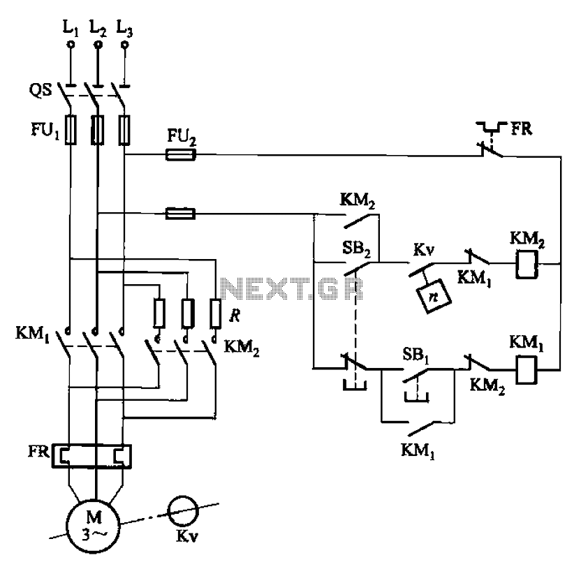
The circuit depicted in Figure 3-124 operates without an intermediate relay. Kv serves as the speed relay, activating when the electric motor speed exceeds 120 r/min while the contact is closed. If the speed drops below 100 r/min, the...