
Solar Charger circuit
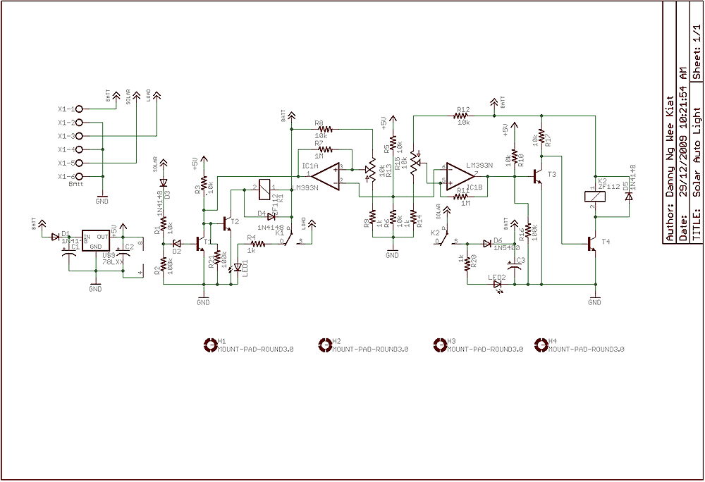
The solar auto lighting project employs a solar panel as the primary energy source, which charges a battery that powers the lighting system. The operation of the circuit hinges on the voltage levels produced by the solar panel, which are monitored to determine the ambient light conditions. A zener diode (D2) is incorporated into the circuit to establish a reference voltage for the light detection mechanism. The zener diode's breakdown voltage is selected to facilitate the transition of the circuit state when the solar panel voltage drops below a predetermined threshold, indicating that it is dark.
Relay K1 plays a crucial role in controlling the load and the battery connection. It is designed to disconnect the load if the battery voltage falls below a specified threshold, preventing over-discharge of the battery and ensuring its longevity. This relay is actuated by a comparator that continuously monitors the battery voltage, enabling automatic disconnection when necessary.
Relay K2 is utilized to manage the charging process of the battery. It operates in conjunction with the comparator, which assesses the battery voltage and determines when it is appropriate to halt the charging. This relay ensures that the battery is not overcharged, thus maintaining optimal battery health and performance.
The comparator circuit is central to the functionality of the entire system, as it performs real-time voltage comparisons to trigger the relays based on the set thresholds for both light detection and battery management. The design of this circuit allows for efficient solar energy utilization while providing a reliable automatic lighting solution that responds dynamically to environmental conditions.Few years back, I had been working on a project for solar auto lighting. The light will turn on when the the solar panel voltage drop below a set point indicating that it is dark. The detection is done by using D2 in the schematic. The zener diode value will be adjusted so that the transition between the switch depends on the amount of light the panel receive.
Relay K1 is used to switch the load and the battery. If the battery power fall below a set threshold, the relay will cut the supply to the load. Relay K2 is used to control the charging of the circuit. When a Set point is reach the charging will be cut off. A Comparator is used for the voltage comparison. 🔗 External reference
Related Circuits
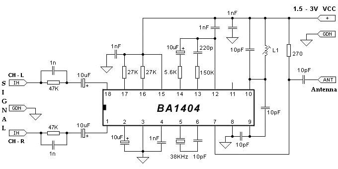
The BA1404 can be utilized to create a simple and effective FM stereo modulator electronic project. This BA1404 FM stereo modulator device operates within the FM broadcast band (75-108 MHz) and requires only a few common external components. The...
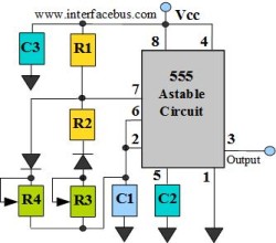
The astable multivibrator circuit lacks a stable state. In the absence of an external signal, the internal transistors alternately switch between cutoff and saturation at a frequency determined by the RC time constants of the coupling circuits. Therefore, an...
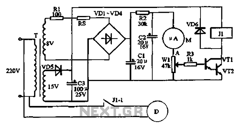
An automatic humidifier can be utilized for humidity control in households, hatcheries, poultry farms, or juvenile poultry houses. When the humidity level falls below 50%, the automatic humidifier activates to maintain a specific humidity level that is beneficial for...
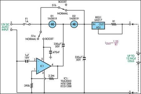
This circuit is designed to charge between one and twelve NiCd cells using a car battery. When switch S1 is in the "normal" position, it can charge up to six cells. The LM317 regulator functions as a simple current...
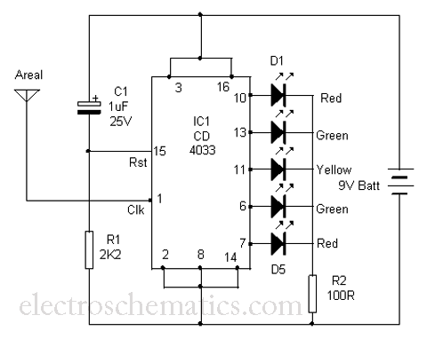
This is a simple tool designed to measure the level of radiation emitted by electrical or electronic devices. The circuit utilizes LEDs to create a running light pattern when it detects electromagnetic radiation from a source. It can detect...
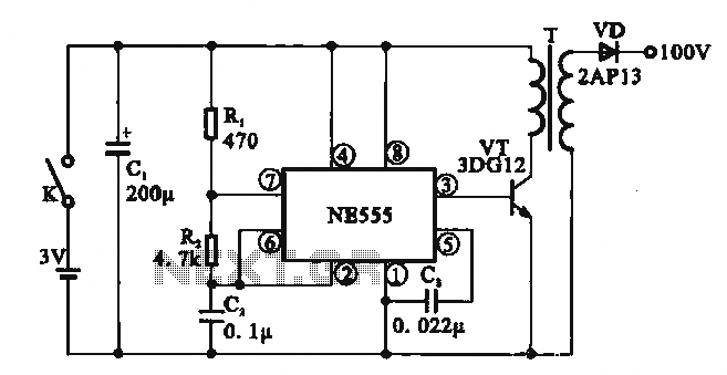
This circuit illustrates a simple boost converter, which is powered by an oscillating signal generated by the NE555 timer. The signal is amplified through a VT transistor to drive a booster transformer. This step-up transformer increases the oscillating signal,...
Warning: include(partials/cookie-banner.php): Failed to open stream: Permission denied in /var/www/html/nextgr/view-circuit.php on line 713
Warning: include(): Failed opening 'partials/cookie-banner.php' for inclusion (include_path='.:/usr/share/php') in /var/www/html/nextgr/view-circuit.php on line 713