
Numitron Clock with Battery Back-up

The described project involves the design and implementation of a digital clock utilizing Numitron displays, leveraging both historical components and modern electronic principles. The clock design integrates the SN7490 decade counter and the SN7447 BCD to seven-segment decoder to facilitate the counting and display of time. The choice of using Numitron displays adds a nostalgic aesthetic, while the implementation of a battery backup ensures continuous operation during power interruptions.
The circuit schematic would begin with the SN7490 connected to a clock source, which could be derived from a 555 timer configured in astable mode to provide a suitable pulse frequency for timekeeping. The output of the SN7490 would be connected to the SN7447 decoder, which translates the binary-coded decimal (BCD) output of the counter into a format that can drive the Numitron displays.
The Numitron displays would require a specific voltage and current to operate effectively, thus necessitating a power supply circuit that can step down the mains voltage. A transformer or a switching regulator could be employed to achieve the desired voltage. The addition of a battery backup circuit would involve a rechargeable battery connected to a charging circuit that activates when mains power is present, and automatically switches to battery power when the mains is disconnected.
The design should also include current-limiting resistors for the Numitron displays to prevent damage from excessive current. The entire assembly would be housed in a suitable enclosure that allows visibility of the displays while protecting the internal components.
Overall, this project not only serves as a practical application of digital electronics but also as a tribute to the history and evolution of display technology in electronic devices.The idea was that you removed the center page from the magazine and cut it into four pieces to obtain a card that would fit into a filing system. The front side of each card would gave the connections to the IC, while the other side would contain technical details and an application circuit.
Fig. 1 depicts, as an example, the front- and back-side of the IC-card for the 74141 nixie driver. Intrigued as I was by the mysterious symbols, these cards enabled me to decipher the basic ideas behind digital electronics. And like most things in life, once you have mastered the basics, the rest comes pretty smoothly. For years I was obsessed by the possibilities of these small black building blocks. It soon became my dream to build a digital counter with display. Now you have to remember that in those days something like a seven segment display was something that not that many people, including myself, had seen in real life.
So for my birthday I asked a SN7490 decade counter, a SN7447 BCD to seven-segment decoder, and a 3015-F Numitron display. In those days these components were rather expensive! In the same Elektuur magazine from which the Fig. 1 IC-card was taken, I have an advertisement which offered these components. In the table below, you will find the prices of these components as they were then in guilders, but also in the price in Euro now, based on the ratio of the prices of the Elektuur magazine then (fl 1.
95) and now (Euro 6. 85). Even if I am mistaken by a factor of two, than still it was a lot of money. I still remember my mother saying that she had never paid so much money for so little. My grandmother on seeing the goods and hearing the price was, I believe, in shock for days. I still have the Minitron display, and it still works fine as you can see below. Looking back and realizing how these experiments skilled me in experimenting, and subsequently were to determine my professional career, I can only but conclude that it was money well spend! Years later my father, who worked at a Shell chemical plant, brought an old discarded data-logger with him home from work for me.
My father was in many ways not an easy man, but he always stimulated me in everything I did, and he was very proud of me. I owe a great deal to him, and I have many happy memories of him. Among others the data-logger contained a small PCB with four DA2300 Numitron displays plus SN7447 seven-segment decoders (Fig.
2). For more than twenty years I have dragged it behind me from home to home. At first I thought it was a piece of old fashioned obsolete technology and I preferred to use modern LED displays instead. Later when I realized what a pretty and romantic devices they really are, I did not dare to use them, because I realized that by using these filament displays I would eventually destroy them.
At last I have an idea how I can use these tubes for a clock and still be assured of a long life time. In my hobby shack I have one central switch that I use to switch everything in the room on and off. If I run my clock from that mains, the tubes will only be on only when I am actually working there (unfortunately not that much actually).
It does however imply that the clock will need a battery backup to keep it running even when the mains is disconnected. On top of that I decided to reduce the supply voltage of the tubes. Figure 3 is taken from the DA2300 datash 🔗 External reference
Related Circuits
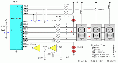
The clock timer utilizes a PIC16F628 microcontroller to display time in a 3.5-digit format and manage an external load. It features a calendar that accounts for leap years and optional daylight saving time adjustments. The timer output can be...
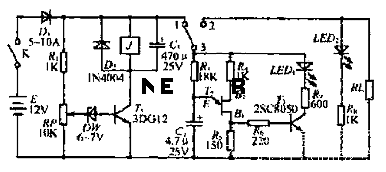
The discharge control circuit consists of a battery management system designed to prevent over-discharge of a battery. It features a relay control mechanism that activates when the battery voltage drops below a specified threshold of approximately 10.5V. The circuit...
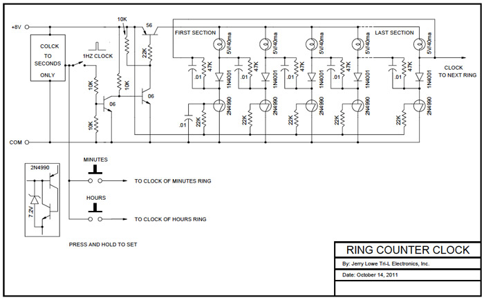
A Ring Counter Clock was designed and built in 1970. The base is a 12-inch diameter, 2-inch thick block of walnut sourced from a hollowed-out gun stock blank. The backside of the base has been hollowed out to accommodate...
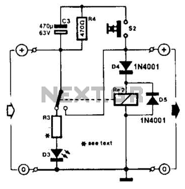
A charged capacitor C3 and a momentary pushbutton switch S2 are utilized to temporarily activate relay RE2. The battery being charged powers the relay to maintain its closed state. Additionally, S2 can energize the relay even if the battery...
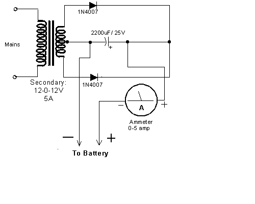
This very simple circuit uses a transformer, two diodes, a capacitor, and an ammeter. To charge a battery, just connect the + and - terminals of the circuit to the corresponding terminals of the battery. When the battery is...
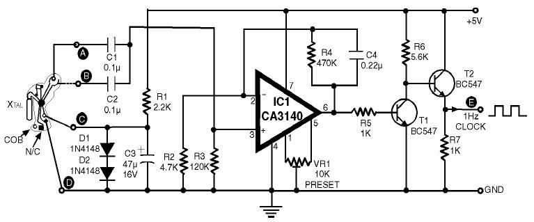
1Hz Clock Generator Circuit with Chip On Board (COB). The COBs used in different watches may differ somewhat in their configuration. However, through trial and error, one can identify the appropriate points corresponding to points A, B, C, and...