Low battery indicator

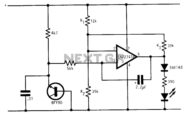
Under optimal battery conditions, the LED remains off. As the battery voltage decreases, the LED starts to flash, and when the battery reaches a low voltage condition, the LED illuminates continuously. This circuit is designed for use with a 9-volt battery, and with the specified component values, the LED flashes when the voltage drops between 7.5 to 6.5 volts.
The circuit utilizes a BFY90 transistor, which acts as a switch to control the LED based on the battery voltage level. The transistor is configured in such a way that it remains off when the voltage is above 7.5 volts. When the voltage falls below this threshold, the transistor begins to conduct, causing the LED to flash intermittently. This flashing behavior serves as an early warning signal to indicate that the battery is nearing a low voltage condition.
As the voltage continues to drop to 6.5 volts or lower, the transistor remains fully on, allowing the LED to light continuously. This provides a clear indication that the battery is in a low voltage state and may require replacement or recharging. The integrated circuit used in this design is the SN72741P, which is responsible for monitoring the voltage levels and controlling the timing of the LED's flashing behavior.
The circuit can be further enhanced by incorporating additional components, such as resistors and capacitors, to fine-tune the flashing frequency and brightness of the LED. Proper selection of these components is crucial to ensure reliable operation across the specified voltage range. Additionally, the circuit layout should minimize parasitic capacitance and inductance to maintain performance, especially in portable applications where battery life is critical.Under good battery conditions the LED is off. As the battery voltage falls, the LED begins to flash until, in the low battery condition, the LED lights continuously. Designed for a 9-volt battery, with the values shown the LED flashes from 7.5 to 6.5 volts. The transistor is the BFY90 and the IC is the SN72741P.


