
how to make simple piezo buzzer circuit

The piezoelectric buzzer circuit exemplifies a straightforward yet effective design for sound generation through oscillation. The use of a single transistor simplifies the circuit, making it accessible for basic electronic projects. The choice of a three-terminal piezo element is vital, as it allows for feedback that sustains oscillations, a critical aspect of the circuit's operation. The transistor acts as a switch that alternates between conducting and non-conducting states, driven by the feedback from the piezo element. This rapid switching creates a cycle of energy transfer between the transistor and the inductor, enhancing the sound output.
The construction of the circuit can be achieved on a small PCB or a breadboard, with careful attention to the placement of components to minimize interference. The inductor, or buzzer coil, should be chosen based on its inductance value to ensure optimal oscillation frequency. The piezo element's mounting on a rubber ring not only aids in sound amplification but also helps dampen vibrations, preventing damage to the component.
This circuit can be further explored by experimenting with different inductor values or piezo configurations to modify the sound characteristics. Additionally, integrating a variable resistor could allow for the adjustment of the frequency, providing a wider range of sound effects. Overall, this simple piezoelectric buzzer circuit serves as an excellent introduction to the principles of oscillation and sound generation in electronic design.A very simple piezo electric buzzer using hardly any electronic components. Just a single transistor, a coil, a piezo buzzer are enough to make it buzz or rather twit for you, with an output that may be quite ear piercing. The simple buzzer circuit described here actually works in a quite unique way. Instead of the normal working concept employed by other forms of oscillators which require resistor and c
apacitor networks for generating the oscillations, this circuit use inductive feedback for the required operations. Referring to the above simple piezo buzzer circuit we find that the transistor T1 along with the inductor forms the heart of the circuit.
Basically the coil which is specifically called the buzzer coil, is in fact positioned for amplifying the created oscillations while the actual feed back is provided by the center tap of the three terminal piezo element used for the present application. When a voltage is introduced in the circuit, the transistor conducts, operating the piezo element across the buzzer coil, however this also leads to the grounding of the base of the transistor through the center tap of the piezo element, this instantly switches off the transistor and in turn the piezo also switches off, releasing the base of the transistor.
The center tap from the piezo transducer plays an important role in sustaining the oscillations and therefore in this particular design we need a three terminal piezo rather than a two terminal one. The oscillations produced at the collector of the transistor is dumped into the coil, saturating the coil with magnetic inductions.
The coil kicks back the stored energy during the oscillations, magnifying the generated AC across it. This stepped up AC is applied across the anode and the cathode of the piezo element, which starts vibrating sharply according the pitch of the frequency, generating a shrill, ear piercing sound in the air.
For this particular application the piezo element needs to be stuck at the base of its housing which must consist of a hole having a diameter of about 7 mm. The piezo element cannot be stuck directly over the base of the housing, rather it must stuck and positioned over a soft, pure rubber ring, having diameter 30 % less than that of the piezo transducer.
🔗 External reference
Related Circuits

Nokia BL-4C and BL-5C are 3.7V, 700-1000mAh (various) lithium-ion batteries that have three terminals. These terminals include a positive terminal, a ground, and a BSI (Battery Status Indicator) terminal, which presents a fixed resistance value that needs to be...

The LM12 audio amplifier circuit is designed to deliver high output power for loads with impedances of 4 ohms or 8 ohms. The maximum output power achievable by this amplifier is approximately 60 watts for a 4-ohm load and...
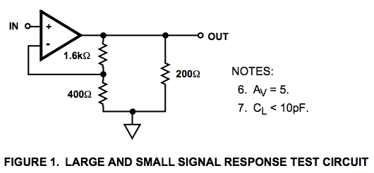
Here is a circuit diagram for a signal response test circuit from the specification sheet for a HA-5195 operational amplifier. It appears to be a non-inverting amplifier circuit with a gain of 5, along with a 200-ohm resistor connecting...

Wireless audio and visual transmission to a TV. The TV functions as a receiver, eliminating the need for a separate monitor. It can also be connected to a VCR or CCD camera, enabling the setup of a remote CCTV...

The modem off indicator is designed specifically for avid Internet users. The circuit for this indicator is remarkably simple, and its simplicity may lead to significant cost savings by providing a clear visual indication of whether the telephone line...

The main speed setting box FR-FG and the linkage setting operation box FR-AL (Mitsubishi inverter) enable synchronous operation of multiple motors. The circuit is illustrated. By utilizing these two external units, the speed of the primary motor (main motor...