
indicator circuit

The modem off indicator circuit is a straightforward yet effective solution for monitoring the status of a telephone line in relation to modem activity. The primary components of the circuit include a green LED, a bridge rectifier, and a current-limiting resistor (R1).
The bridge rectifier is crucial as it converts the alternating current (AC) from the telephone line into direct current (DC), allowing the LED to function regardless of the line's polarity. This feature simplifies the design and enhances reliability, as it removes the need for additional components to protect against reverse polarity.
The use of a high-efficiency LED is particularly advantageous in this application. By requiring only 2 mA for illumination, the circuit minimizes the load on the telephone line, ensuring that it does not interfere with normal telephone operations. Resistor R1 is selected to limit the current flowing through the LED to this optimal level, thus ensuring longevity and consistent performance of the indicator.
When the telephone line is idle, the voltage present allows the LED to light up, providing a clear visual cue to the user. Conversely, when a call is initiated, the voltage drops, extinguishing the LED and indicating that the line is busy. This functionality is essential for users who rely on their modem for Internet access, as it prevents unnecessary charges that could accumulate if the modem remains active while the line is in use.
Overall, the modem off indicator circuit is an elegant solution that combines simplicity with functionality, making it an invaluable tool for managing telephone line usage effectively. Its design ensures minimal impact on the telephone line while providing crucial information to the user.The modem off indicator is intended especially for serious Internet surfers. It will be seen that the circuit of the indicator cannot be much simpler, or there might be nothing left. In spite of its simplicity, it may prove to be a cost-saving device, since it shows at a glance whether the telephone line is free again after the modem has been used
. This obviates high telephone charges in case for some reason the modem continues to operate. The circuit depends on the fact that there is a potential of about 40 V on the telephone line when it is not busy. This voltage drops sharply when a telephone call is being made. If, therefore, the circuit is linked to telephone terminals a and b, the lighting of the green LED shows that the line is not busy in error.
The bridge rectifier ensures that the polarity of the line voltage is of no consequence. This has the additional benefit that polarity protection for the LED is not necessary. To make sure that the telephone line is not loaded unnecessarily, the LED is a high efficiency type. This type lights at a current as low as 2 mA, and this is, therefore the current arranged through it by resistor R1. 🔗 External reference
Related Circuits
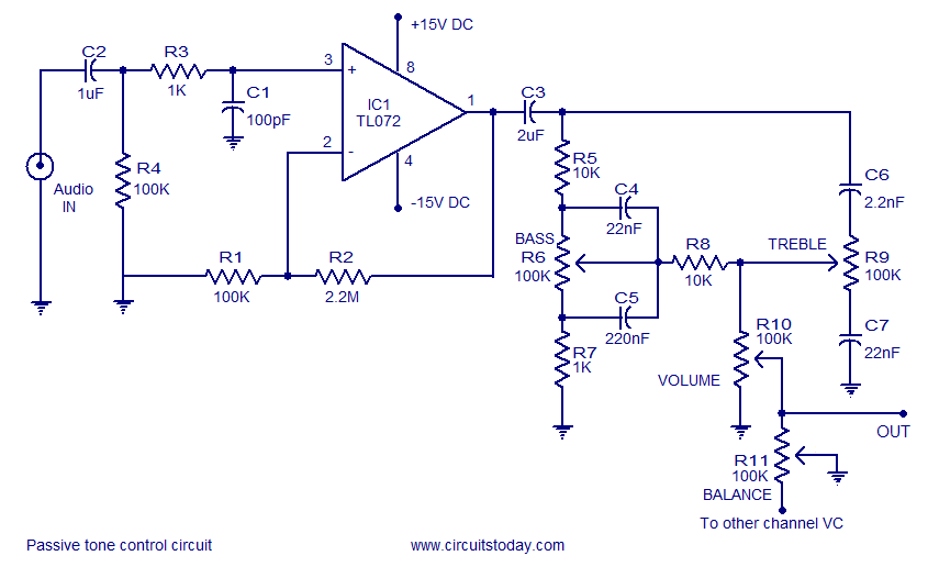
Tone control circuit utilizing an operational amplifier and a Baxandall passive tone control configuration. The overall gain is 25 dB, with a boost and cut capability of 20 dB. The circuit is powered by a dual 15V supply. The tone...

This design circuit functions to filter out interference signals, ensuring that the signal received from a Morse code station is distinct. The circuit utilizes the earliest mode of radio communications, which employs Morse Code on a continuous wave carrier...
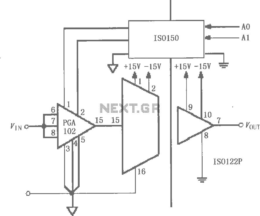
The circuit features grounds ISO122/124 and PGA102, with ISO150 forming a gain programmable channel isolation circuit. The input signal VIN is amplified by the instrumentation amplifier PGA102 to ISO122P, which then outputs VOUT from the isolation amplifier ISO102P. Two...
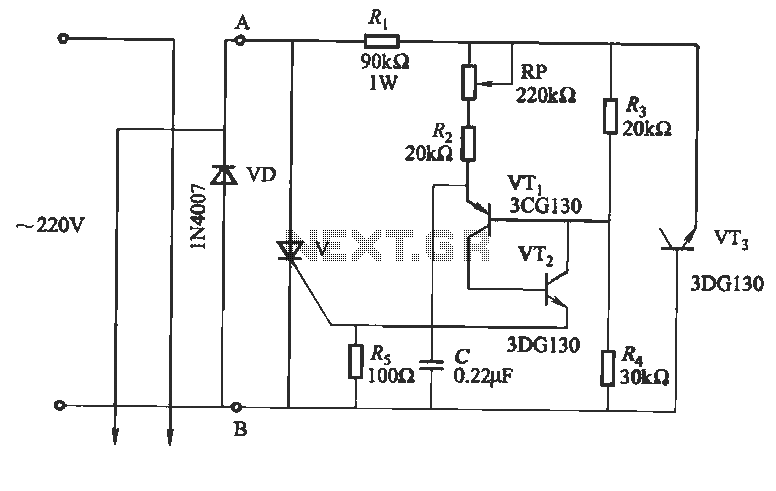
This circuit utilizes an "and other potential triggers" circuit. The term equipotential trigger refers to a crystal bidirectional thyristor trigger, which can be activated by either a positive or negative trigger. In this setup, the control electrode G and...
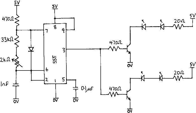
The infrared receiver requires the infrared light to be modulated at 38 kHz, which corresponds to a period of 26 µs. The specifications for the receiver suggested using a 50% duty cycle; however, this configuration did not perform as...
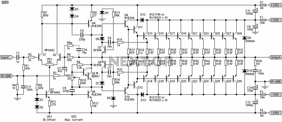
This 1500W Power Amplifier Circuit Diagram contains two images of the circuit. For more complete information, refer to the main post titled "1500 Watt Power Amplifier." It includes a list of component parts for the 1500W Power Amplifier Circuit...