
How to Read a Schematic

The symbols representing the guitar indicate components of a quarter-inch jack. One part of the jack connects to ground, linking it to all circuit parts represented by the ground symbol. This connection illustrates the return path for current flowing back to the guitar. The portion of the current considered the signal flows from the tip of the plug into the upper part of the schematic. Each zigzag line signifies a resistor, a simple device designed to provide a specific resistance. Resistors control the proportion of current or signal that traverses each branch of the circuit. Resistor R1 establishes the input impedance, or the load that the device presents to the guitar. Two lines interrupting the circuit line represent a capacitor, which primarily serves to block low-frequency signals. In this circuit, the goal is to prevent any constant voltage (DC) from the guitar from affecting the active components and vice versa. The frequency that will be blocked depends on the values of R2 and R1. Capacitor values are typically given in microfarads, denoted by the Greek letter mu (μ) followed by 'f'. However, many software programs incorrectly display this, substituting 'm', which refers to millifarads instead of the intended microfarads.
The triangle symbol represents an operational amplifier (op-amp), a complex integrated circuit that is straightforward to use. The signal connects to one of the two inputs and appears at the output. A feedback connection from the output back to the inverting input (indicated with a minus sign) regulates the gain of the op-amp. Connecting the output directly to the inverting input sets the gain to unity, meaning no change in signal level. The op-amp in this circuit is designed to reduce the current supplied by the guitar. The resistor with an arrow in the middle is a variable resistor or potentiometer, commonly associated with control knobs. The arrow can be visualized as moving across the resistance, allowing for a varying proportion of current to be drawn off, or the voltage at the arrow to change. This configuration represents a typical volume control. Adding resistors to the feedback loop of an op-amp results in gains other than unity, with the ratio of R4 to R5 determining the gain. U2 provides the necessary power to drive the speaker, while the final resistor, R7, safeguards the speaker from excessive current and protects the op-amp from potential damage due to overcurrent. To distinguish power supply connections from signal connections, solid arrows indicate power busses (a bus is a wire or trace connecting multiple points in a circuit). All upward-pointing arrows are interconnected, as are all downward-pointing arrows. In more complex circuits, this technique is commonly employed, often with numbered or lettered connections for clarity.Electronic circuits are presented in schematic form. A schematic is really a map showing the path the current takes through the various componenets. Each component is represented by a symbol, usually with either a label or a value (or both). The arangement of the components on paper is chosen to make the function of the circuit clear, and usually only vaguely resembles the actual construction of the device. The current path is shown with lines, again drawn for maximum clarity, with little concern for the length or position of the real wires. The layout of a schematic is designed to show the function, usually with signal progressing from left to right.
The actual layout of the circuit will be quite different. All points on a line are electrically identical. This includes all branches of a line. When we discuss the properties of circuits, we will assume the wires are perfect conductors, with no resistence or propagation delays of any kind. In fact, when we talk about real wire, we will make drawings the show ideal wire with components connected illustrating various effects.
This symbol is ground. All ground points in the schematic are connected together. Furthermore, these points represent places in the circuit that are at 0 volts for reference in measurements. Often the ground includes the metal chasis of a device, but not always. Labels. Each component should have a label, and there is a standard set of names. For instance, a resistor is labeled R, and this circuit has 7 of them. Presumably there is a table somewhere that tells what the values are. There is only one capacitor; instead of calling it C1, I just listed its value. The gizmo at the left of figure 1 represents a phone jack. The label implies a guitar will be connected here. You have to understand that "signal" is not the same as "current". The current is the flow of electrons, the signal is the flow of information. The current is going every which way in this circuit, alternating directions in fact. The signal is supposed to come from the guitar and wind up at the speaker on the far right. The route is complex, with each component working with others to modify the signal in some manner. (If your get nothing out of this essay but the fact that it is the combination of components that modifies the signal, you are ahead of the game.
) Let`s work our way through : The symbols at Guitar in represent the parts of a quarter inch jack. Notice that part of the jack is connected to ground (This is the part that connects to the outer shield of the cable). Remember that means it is actually connected to all parts of the circuit with the ground symbol. This is the path the return current takes, in essence flowing back to the guitar. The part of the current we consider the signal flows from the tip of the plug into the upper part of the schematic.
Each zig zag line represents a resistor. This is a simple device that has a desired resistance. These serve to control the proportion of current or signal that follows each branch of a circuit. Resister 1 establishes the input impedance, or the load that this device shows to the guitar. Two lines interrupting the circuit line represent a capacitor. Most of the time the feature of acapacitor we are most interested in is the ability to block low frequency signals. In this case, we want to keep any constant voltage (DC) from the guitar away from the active components, and any DC the active components may have away from the guitar.
The actual frequency that will be blocked depends on the values of R2 and R1. (Note: values for capacitors are given in microfarads. The proper symbol for this is the greek letter mu and an f. many programs don`t proprery display this, turning the mu into an m. which strictly speaking would be "milifarads", however, microfarads is the usual intention. ) The trangle represents a rather complicated integrated circuit called an operational amplifier. They are complicated to design and make, but pretty simple to use. The signal is connected to one of the two inputs, and appears at the output. A connection from the output back to the inverting input (with the minus sign) controls the amout of gain the op amp will give us. This kind of connection is called feedback. Simply connecting the output to the inverting input sets the gain at unity- no change in the signal level.
The purpose of the op amp in this circuit is to reduce the amount of current the guitar must supply The resistor with an arrow in the middle is a variable resistor or potentiometer. This is the thing that most control knobs are atttached to. If you conceive of the arrow as moving up and down across the resistance, you can visualize a varying proportion of the current being drawn off, or the voltage at the arrow changing.
The configuration shown is a typical volume control. Adding resistors to the feedback of an opamp gives gains other than unity. In this case, the ratio of R4 to R5 sets the gain. U2 provides the muscle in this circuit, providing power to drive the speaker. The last resistor, R7, protects the speaker from too much current. It also protects the op amp, which may be cooked if it is asked to provide too much. To keep the power supply connections distinct from the signal connections, I have used the solid arrows to indicate power busses (a buss is a wire or trace that connects to several places in a circuit. ). All of the upward pointing arrows are connedted together, and all of the downward pointing arrows are connected.
In complex circuits you will see a lot of this trick, often with numbered or lettered connections. 🔗 External reference
Related Circuits
This simple circuit tests speakers, microphones, transformers, and voltage. It is essentially a very low-frequency oscillator that produces extremely short "fruity" pulses. The sound produced is easy to hear and allows for precise determination of its direction, making it...
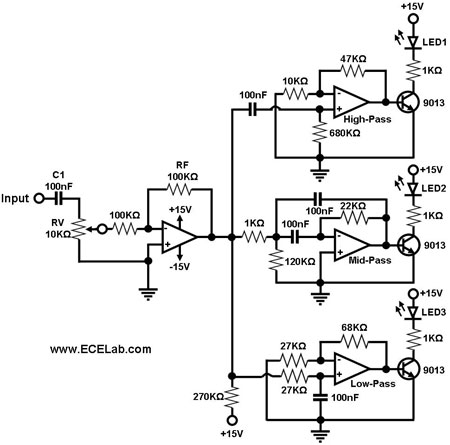
Figure 1 illustrates a simple circuit designed for converting an audio signal (such as one from the output terminals of a CD player). The circuit primarily consists of a buffer/amplifier stage and three filtering circuits: a high-pass filter, a...
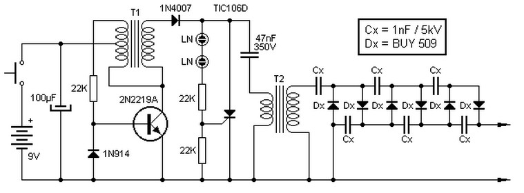
This high voltage source consists of an inverter built around a transistor that generates pulses of 150V. These pulses are supplied to an inverter made of a thyristor and a capacitor, which is connected in series with transformer T2....
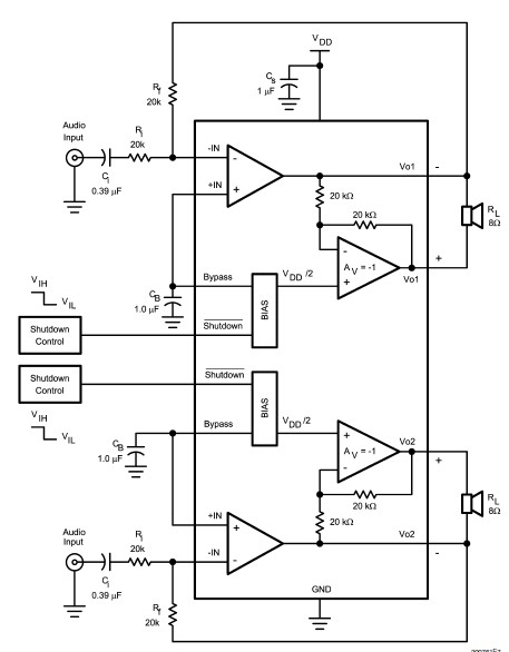
The LM4992 stereo audio power amplifier can be utilized to design a straightforward audio power amplifier project suitable for portable electronic devices. This amplifier circuit is capable of delivering 1 watt of continuous average power per channel to an...
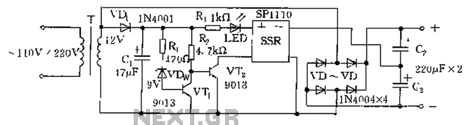
The circuit is automatically converted to a low-voltage configuration. A 220V AC supply is stepped down by transformer T. After this, the breakdown voltage of diode VDw causes transistors VT1 and VT2 to turn off, resulting in the solid-state...
Here they exist two regulator circuits, that use the IC L200, as regulator of voltage and current, the company SGS-Thomson, which give these circuits. In circuit Fig.1, we can regulate the output voltage, with the RV1, while in the...