
How to Wire a PIC Microcontroller
The circuit design for the PIC 16F627 controlling three LEDs involves several key components and connections. The microcontroller operates at a voltage level compatible with the 3.3V LEDs, which require appropriate current limiting to prevent damage. Although the initial testing with 1.5V AA batteries indicated that the LEDs functioned without resistors, it is crucial to incorporate current-limiting resistors in the final circuit to ensure safe operation under varying conditions.
For the design, it is recommended to use 220Ω to 330Ω resistors in series with each LED. This will help maintain the current within the safe operating limits of the LEDs, which typically range from 20mA to 30mA. The circuit should be structured as follows:
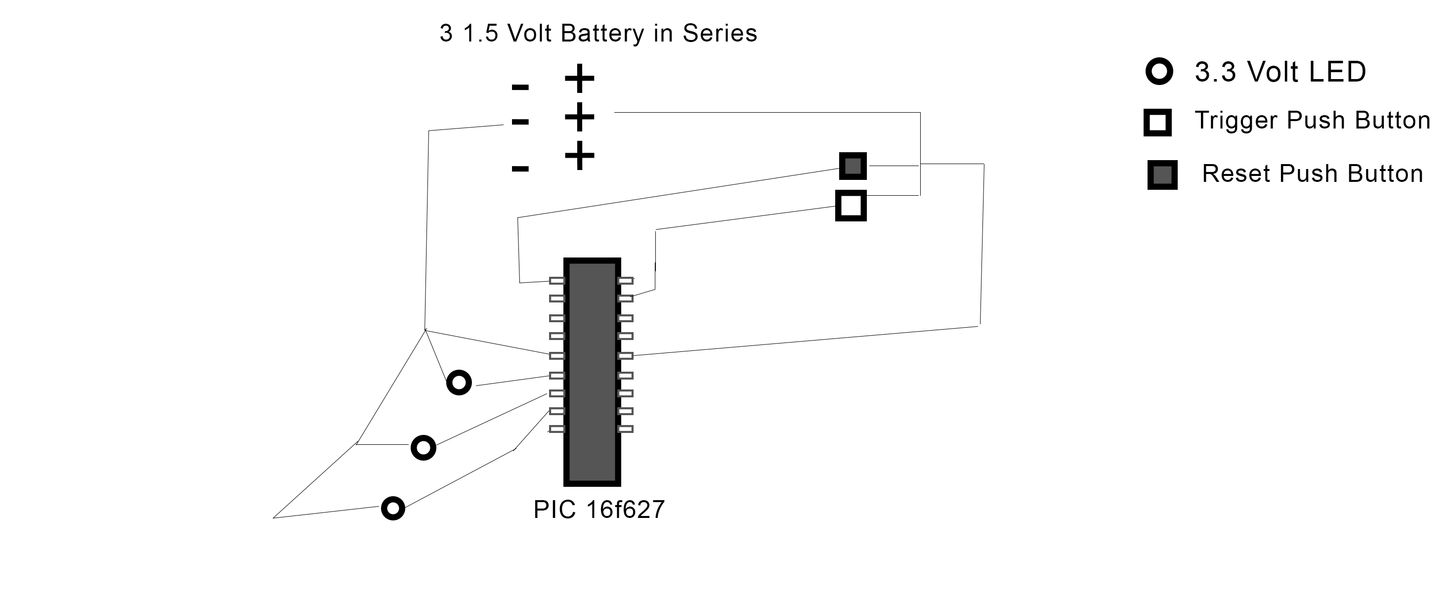
1. Connect the anode (long lead) of each LED to the corresponding output pin of the PIC (RB0, RB1, RB2).
2. Connect the cathode (short lead) of each LED to one terminal of the current-limiting resistor. The other terminal of each resistor should be connected to the ground (GND).
3. For the pushbuttons, connect one terminal of the trigger button to pin RA0 and the other terminal to ground. Repeat this process for the reset button with pin RA2.
4. Ensure that the microcontroller's power supply is stable, using a regulated 5V supply if needed. Connect the VDD pin of the PIC to the positive supply and the VSS pin to ground.
The software logic in the provided code is structured to monitor the state of the pushbuttons and control the LEDs accordingly. It is essential to ensure that the button states are read correctly and that debouncing is implemented if necessary. This can be done by introducing a short delay after reading the button state to avoid false triggering caused by mechanical bounce.
The configuration of the TRIS registers is correctly set to define the direction of each pin, with TRISB set to output for the LED pins and TRISA configured as input for the buttons. The main loop continuously checks the state of the buttons, toggling the LEDs on and off based on the button presses.
In summary, the successful transition from a breadboard setup to a more permanent circuit requires careful consideration of component specifications, proper circuit design, and thorough testing to ensure functionality.I managed to program my PIC 16f627 to turn on three LEDs when push button (trigger button) is pressed and start a shut down sequence (basically each LED toggles off one after another with a 5 second delay in between) when another pushbutton is pressed (reset button). I`ve been testing this on a Velleman`s K8048 PIC Programmer/ Experimentat ion board. PINs RA0 and RA2 are the inputs for the trigger and reset pushbuttons respectively while pins RB0, RB1, and RB2 are the output pins for the LEDs. Working with the experimentation board is great but I want to move this to an actual circuit. The problem is I have no idea where to start. I`ve bought 3 LEDs (3. 3 Volts each), some pushbuttons, and wire and I`ve constructed the following circuit: In the circuit I constructed, I first tested to see if the LEDs would work with 3 1.
5 Volt AA batteries and they worked fine so I figured resisters wouldn`t be necessary. This does not work, however, and I`m totally lost. For reference, here is my code for the PIC. Its written in C using MikroC. It works on the experimentation board so I don`t think its a problem void main() { TRISB. RB0 = 0; TRISB. RB1 = 0; TRISB. RB2 = 0; PORTB. RB0 = 0; PORTB. RB1 = 0; PORTB. RB2 = 0; CMCON = 0x07; TRISA = 255; for(;){ if(PORTA. RA0 = 1 && PORTB. RB0 = 1 && PORTB. RB1 = 1 && PORTB. RB2 = 1){ delay_ms(5000); PORTB. RB0 = 0; delay_ms(5000); PORTB. RB1 = 0; delay_ms(5000); PORTB. RB2 = 0; } if(PORTA. RA2 = 1){ PORTB. RB0 = 1; PORTB. RB1 = 1; PORTB. RB2 = 1; } } } 🔗 External reference
Related Circuits

This is a design circuit for an alarm. This circuit is intended for an anti-theft wireless alarm that can be used with any vehicle operating on a 6 to 12 volt DC supply system. A mini VHF FM radio-controlled...
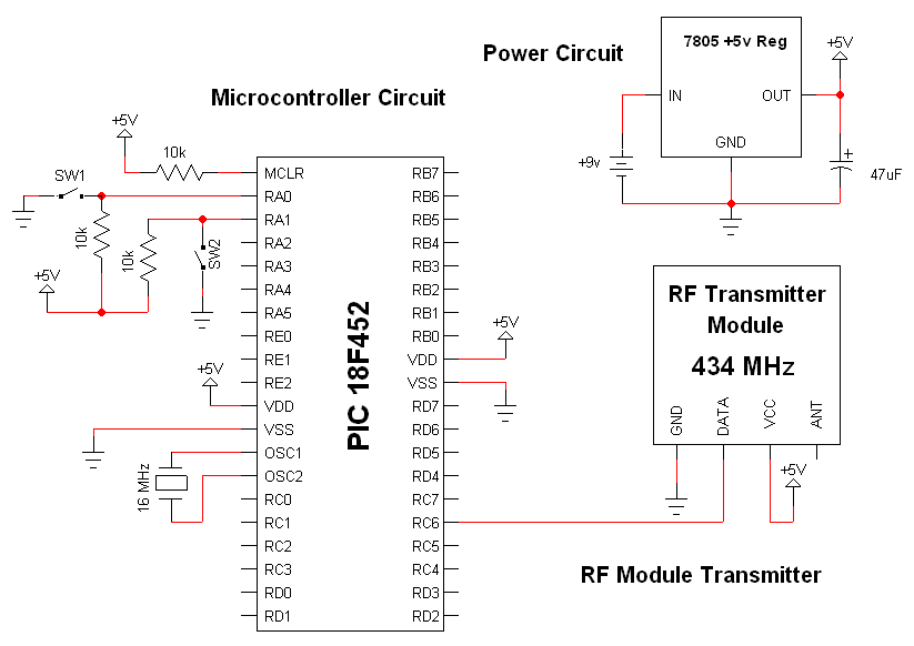
The RF modules utilized in this schematic are straightforward, requiring only a few additional pins for power, ground, and data connections. The primary components featured in this schematic include the RF transmitter module, the RF receiver module, and the...

Electrical signals travel along the neurons in the brain and body, continuously transmitting information throughout the complex system. Without these signals, the body would function like a plant, with different parts unaware of each other's conditions, making animal life...

In many situations, a human interface is required for microcontroller projects. This example describes the interfacing of an AVR microcontroller with a standard PC AT keyboard. According to the keyboard timing diagram, the keyboard transfers data to the host...

A control system is required using a standard PIC microcontroller for managing a LEGO light sensor. Guidance on the implementation process is needed. To control a LEGO light sensor with a standard PIC microcontroller, several key components and steps must...

This project is a simple, inexpensive, and engaging circuit designed for home experimenters or hobbyists. It functions as a basic transmitter capable of transmitting speech over a short distance, effectively serving as a cordless microphone. The circuit employs two...