
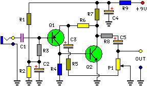
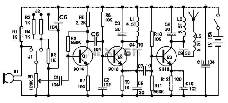
FM Wireless Microphone

The circuit design integrates the MAX4467 and MAX2606 to create a compact and efficient wireless audio transmission system. The MAX4467 serves as the initial signal amplifier, boosting the audio input from the microphone to a suitable level for modulation. This amplification stage is critical for ensuring clarity and strength of the transmitted audio signal. The VCO, represented by the MAX2606, generates the carrier frequency necessary for FM transmission. The inductor L1 plays a vital role in determining the oscillation frequency; careful selection and construction of this component are essential for achieving the desired performance characteristics.
The inclusion of a potentiometer for channel selection and volume control allows users to tailor the output to their specific needs, enhancing the versatility of the device. The design emphasizes the importance of minimizing stray capacitance and optimizing component placement, which are crucial for maintaining signal integrity and transmission quality. The compact nature of the circuit, combined with its low power consumption, makes it an ideal candidate for portable applications, particularly in scenarios where battery life is a concern.
Overall, this circuit represents an accessible entry point for hobbyists interested in wireless audio transmission, providing both educational value and practical functionality. The project encourages experimentation and innovation, allowing users to explore the principles of RF communication in a hands-on manner.A very simple, inexpensive and interesting project which provides lot of fun to a home experimenter or hobbyist. This simple transmitter can transmit speech over a short range. It can be used as a simple cordless microphone. The circuit uses two integrated circuits from Maxim. IC1 a MAX4467, is an amplifier raising the microphone signal to a level suitable for frequency modulation (FM). IC2 is a voltage-controlled oscillator (VCO) with integrated varactor (a. k. a. varicap diode). Its nominal frequency of oscillation is set by inductor L1. The inductor value 390 nH provides an oscillation frequency of about 100 MHz. For best performance, L1 should be a high-Q component. L1 may consist of 4 turns of silver-plated wire wound around a 10-mm drill bit, and stretched to a length of about 1. 5 cm. The wire diameter can be anything between 26 SWG (0. 5 mm) and 20 SWG (1 mm). No core is used. The MAX4467 is a micro-power opamp for low voltage operation and providing 200-kHz gain bandwidth at a supply current of just 24 µA.
When used with an electret microphone, some form of DC bias for the microphone capsule is necessary. The MAX4467 has the ability to turn off the bias to the microphone when the device is in shutdown mode. This can save several hundred micro-amps of supply current, which can be significant in low power applications particularly for battery powered applications like cordless microphones.
The MIC-Bias pin provides a switched version of Vcc to the bias components. Resistor R1 resistor limits the current to the microphone element. The output impedance of the MAX4467 is low and well suited to driving cables over distances up to 50 m. The MAX2606 intermediate-frequency (IF) voltage-controlled oscillators (VCO) has been designed specifically for portable wireless communication systems.
The IC comes in a tiny 6-pin SOT23 package. The low-noise VCO features an on-chip varactor and feedback capacitors that eliminate the need for external tuning elements. Only an external inductor (here, L1) is required to set the oscillation frequency and produce a properly operating VCO.
To minimize the effects of parasitic elements, which degrade circuit performance, place L1 and C5 close to their respective pins. Specifically, place C5 directly across pins 2 (GND) and 3 (TUNE). Potentiometer P2 then lets you select a free channel by tuning over the FM band of 88 MHz to 108 MHz.
Output power is about 21dBm (approx. 10 µW) into 50 . P1 serves as a volume control by modulating the RF frequency. Signals above 60mV introduce distortion, so the pot attenuates from that level. To decrease stray capacitance, minimize trace lengths by placing external components close to IC1`s pins. Using a wire antenna of about 75 cm the transmitter should have a range of about 35 m. Try to keep all leads as short as possible to prevent stray capacitance. The transmitter operates on a single supply voltage in the range 4. 5 V to 5. 5 V from any standard battery source. The transmitter must be housed in a metal case, with shielding installed between the two stages (AF and RF).
Try to keep all leads as short as possible to prevent stray capacitance. Be the first of your friends to get free diy electronics projects, circuits diagrams, hacks, mods, gadgets & gizmo automatically each time we publish. Your email address & privacy are safe with us ! 🔗 External reference
Related Circuits
This circuit is primarily designed to provide a microphone input for standard home stereo amplifiers. Utilizing a battery supply minimizes the risk of low-frequency hum interference from mains power, simplifying the connection to the amplifier by eliminating the need...
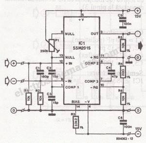
The microphone preamplifier circuit design presented in this schematic utilizes the SSM2015 produced by Precision Monolithics Inc. (PMI), which offers high amplification. The SSM2015 is a low-noise, low-distortion integrated circuit designed specifically for microphone preamplification. It features a differential input...
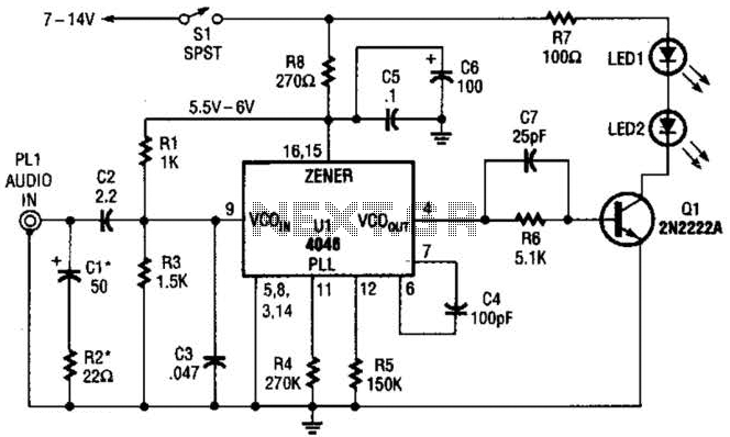
The transmitter for the wireless headphones is constructed using a CD4046 CMOS phase-locked loop, which is paired with a driver transistor and a set of infrared LEDs. While the CD4046 contains two phase comparators, a voltage-controlled oscillator (VCO), a...
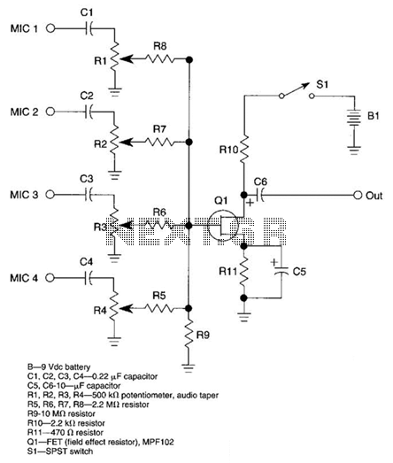
A JFET transistor is utilized as a high-to-low impedance converter and signal mixer. The input impedance is approximately 50.0 kΩ, which can be increased by adjusting resistors R5 to R8 up to 10 MΩ. The output impedance is around...
Many things can go wrong in a modern recording studio, but few are as difficult to track down as reversed microphone polarity. When a microphone is placed in front of a sound source, a positive pressure on its diaphragm...
The design of an FM radio transmission frequency band enables compatibility with any FM radio receiver, allowing the high-frequency signal to be transmitted and restored from an audio signal. This technology serves various applications. Applications of a wireless microphone...