
How to Wire This Latching Relay

The schematic for controlling a water solenoid valve with two water level switches can be outlined as follows:
1. **Components**:
- **Water Level Switch (Top)**: This switch is normally open (NO) and will close when the water level reaches its maximum height. It is connected to the relay's input to signal the relay to deactivate the solenoid valve.
- **Water Level Switch (Bottom)**: This switch is normally closed (NC) and will open when the water level drops to its minimum. It is also connected to the relay's input to signal the relay to activate the solenoid valve.
- **Relay**: The relay serves as an interface between the water level switches and the solenoid valve. It will control the power to the solenoid based on the signals received from the switches.
- **Solenoid Valve**: This valve controls the flow of water and is connected to the output of the relay. When the relay is activated, the solenoid opens to allow water to flow into the tank.
- **Mains Power Supply**: The mains power connects to the relay, providing the necessary voltage to operate the relay and solenoid valve.
2. **Connections**:
- The top water level switch (NO) connects to one terminal of the relay coil, while the other terminal of the relay coil connects to the ground. When the water reaches the top, the switch closes, energizing the relay and opening the solenoid valve.
- The bottom water level switch (NC) connects in parallel with the top switch but to the same terminal on the relay. When the water level is low, this switch remains closed, allowing the relay to be energized. When the water level rises and the top switch closes, the relay is deactivated.
- The solenoid valve connects to the relay's output terminal, allowing it to control the flow based on the relay's state.
- Mains power should be connected to the relay's common terminal, ensuring that when the relay is activated, power is supplied to the solenoid valve.
3. **Resistors**: Typically, resistors are not required on the control side of this circuit unless there are specific requirements for current limiting or voltage division. However, if the switches are not rated for the relay coil voltage, a resistor might be necessary to protect the switches.
This schematic design provides an efficient method to control water levels in a tank using a solenoid valve, ensuring that the water supply is managed effectively based on the predetermined levels. Proper attention to the connections and component ratings is essential for reliable operation.Switch a water solenoid valve using two water level switches, one will be placed at the top of a tank and will be NO (when water level is between full and empty) so that it will send a signal to the relay when the water reaches the top to stop the solenoid. The other switch will be at the bottom of the tank and will be NC so that i t will send a signal to the relay when the water reaches the bottom of the tank to open the solenoid. What I am asking for is this: on that diagram, where do the switches connect Where does the solenoid valve connect Where does mains power connect Lastly, do I need any resistors on the control side of the circuit
🔗 External reference
Related Circuits
This circuit is a wireless car alarm system constructed using two modules: a transmitter module and a receiver module. It operates on FM radio waves and is suitable for vehicles with a power supply of 6-12VDC. A voltage stabilizer...
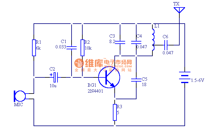
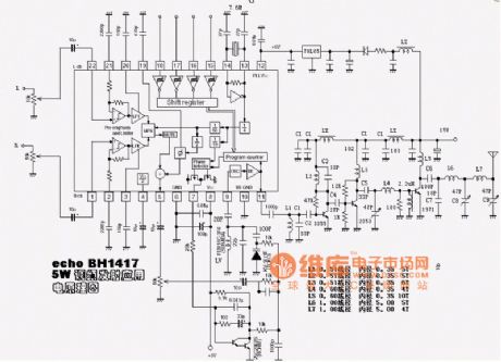
The circuit presented in this document utilizes 12 components to create a compact wireless FM microphone that operates with a stable frequency. The effective transmission range is approximately 30 meters, extending to over 100 meters when powered by a...
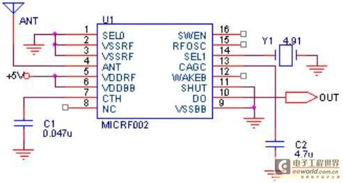
The maximum coverage of the RSR232 serial port transport protocol is 10 meters, which poses significant challenges for remote transmission control. To address this issue, a design has been developed utilizing ultra-high frequency (above 300 MHz) for transmission. This...
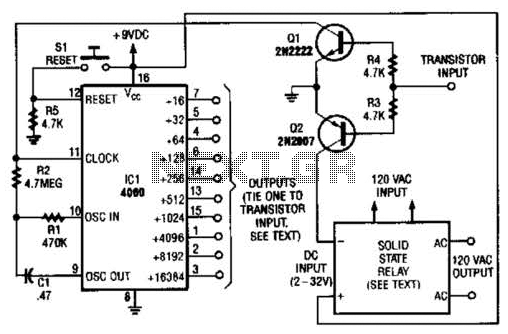
A long-duration timer can be easily constructed using a 4060 CMOS binary divider along with its integrated clock oscillator. The solid-state relay can be selected based on the specific application requirements and may be substituted with a mechanical relay...
A basic circuit of the transistor UHF radio transmitter with a surface acoustic wave resonator (SAW) is presented. The SAW is utilized as a positive feedback element connected between the transistor's base and an LC network in parallel. In...
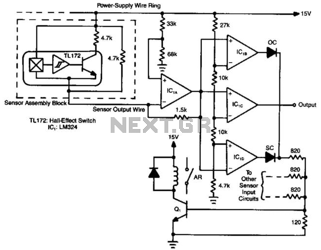
Hall-effect switches offer numerous benefits compared to mechanically and optically coupled switches. However, a significant disadvantage is their requirement for three wires per device. This circuit design reduces the wire count to N+1 wires for N devices. Amplifier IC1A...