
(N + 1) Wires Connect N Hall-Effect Switches

The circuit utilizes Hall-effect switches for their advantages, such as immunity to dust and moisture, and the absence of mechanical wear. The configuration of IC1A as a current-to-voltage converter is crucial for transforming the sensor output into a usable voltage signal. This setup allows for precise monitoring of the current changes that occur when the Hall-effect switch is actuated. The output from IC1A is fed into IC1B, which is configured as a comparator. This comparator is responsible for comparing the output voltage with a reference voltage. When the output current from the Hall-effect switch increases, indicating activation, IC1B detects this change and provides a low output signal, indicating that the switch is engaged.
The fault-detection feature enhances the reliability of the circuit by providing visual feedback through the use of LEDs. Each LED corresponds to a specific sensor output wire, allowing for easy identification of faults in the system. If a wire becomes open, the associated LED lights up, providing immediate notification of the issue. Similarly, if there is a power failure or short circuit, multiple indicators will activate, enhancing the diagnostic capabilities of the circuit.
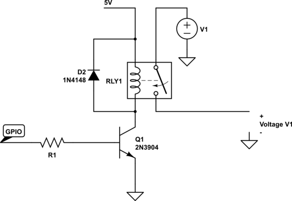
Transistor Q1 plays a critical role in the alarm system. When an LED is illuminated due to a fault condition, Q1 is activated, which can energize the alarm relay, triggering an alert. This mechanism ensures that any fault conditions are promptly addressed, improving the overall safety and reliability of the system. The design effectively minimizes wiring requirements while maintaining functionality and providing essential fault detection, making it a robust solution for applications utilizing Hall-effect switches. Hall-effect switches have several advantages over mechanically and optically coupled switches. Their major drawback is that they require three wires per device. This circuit, however, reduces this wire count to N+1 wires for devices. Amplifier IC1A is configured as a current-to-voltage converter. It senses the sensor assembly"s output current. When the Hall-effect switch is actuated, the sensor"s output current increases to twice its quiescent value. Amplifier IC1B, configured as a comparator, detects this increase. The comparator"s output goes low when the Hall-effect switch turns on. The circuit also contains a fault-detection function. If any sensor output wire is open, its corresponding LED will turn on. If the power-supply line opens, several LEDs will turn on. A short circuit will also turn an LED on. Every time an LED turns on, Ql turns on and the alarm relay is actuated. 🔗 External reference
Related Circuits
A couple of motors were salvaged from an old printer, and there is uncertainty regarding how to connect them to a breadboard and subsequently to a Raspberry Pi. A cobbler kit for the Raspberry Pi is available for this...
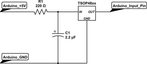
To set up the circuit, a resistor is required; a value of 200 Ohms is suggested, with a supply voltage of 3.3V. The resistor should be connected to the power line and grounded. The data line must be connected...
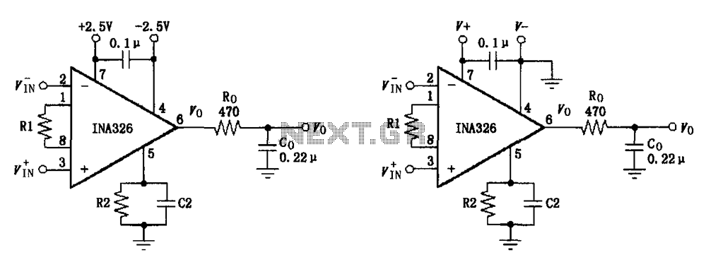
The basic connection circuit for the INA326/327 includes signals and power. A 0.1 µF capacitor is selected for power supply filtering and should be placed as close to the chip's supply pin as possible. Ro and Co serve as...

The power supply terminal should utilize a 1 µF chip capacitor filter, positioned as close as possible to the chip's supply pin. The signal is generated by the input pins 2 and 3. The source resistance of the signal...

The game was originally designed to position three balls locked in holes on a slowly rotating ring around the Deadworld. Once the third ball was secured, a mechanical arm would release them, dropping the balls onto the playfield. This...

The ADP1864 is a compact, cost-effective, constant-frequency current-mode step-down DC-DC controller. It drives a P-channel MOSFET to regulate an output voltage as low as 0.8 V with ±2% accuracy, handling load currents up to 5 A from input voltages...