
Human to Robotic Voice changer circuit
In contrast, artificial speech is limited to a basic synthesis of different voices, resulting in a consistent output that lacks the unique details that contribute to the perfection of natural speech. This circuit introduces speech distortion and modifies the frequency spectrum, leading to a sound that closely resembles a robotic voice.
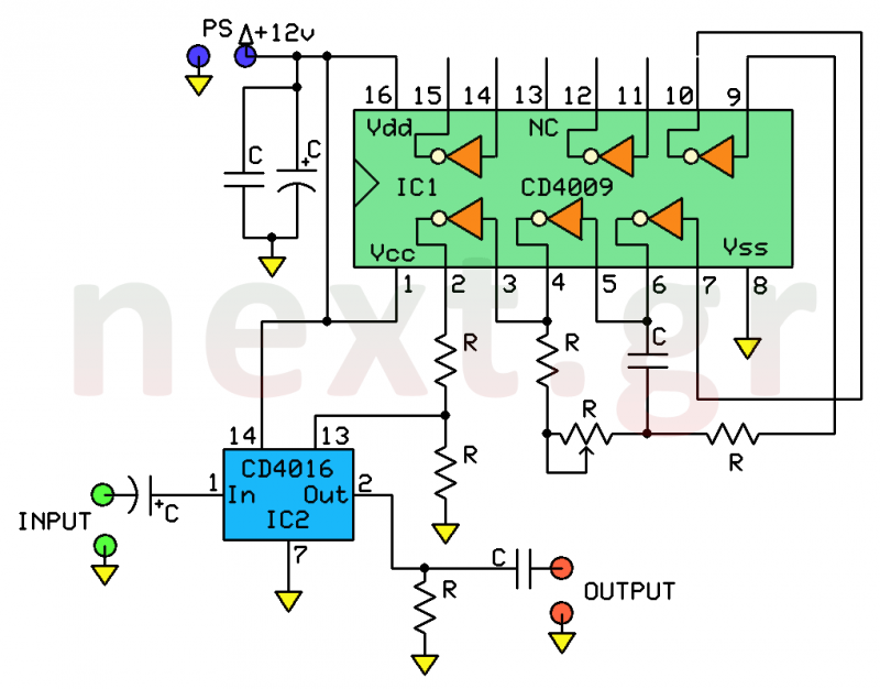
Operation of the circuit is based on two CMOS integrated circuits: IC1 (CD4009) and IC2 (CD4016). The CD4016 is a dual electronic switch that can control the flow of an analog or digital signal from input to output based on the presence of voltage at the control terminal. Internally, this IC contains four switches, although only one is utilized. Terminals 1 and 2 serve as the input and output for the switch, while control voltage—either continuous or pulsed—is applied to terminal 13.
IC1 (CD4009) consists of five inverter isolators. Three of these (N1, N2, N3) create a square-wave RC generator, with the signal frequency determined by components C3, P1, and R2, which can be adjusted between 200 Hz and 20 kHz using the P1 trimmer. The fourth inverter (N4) isolates the generator from the acoustic signal network that flows through IC2 via resistors R3 and R4, which form a voltage divider. A portion of the square wave signal is sent to the control terminal of IC2, allowing the acoustic signal to pass through the electronic switch to the output during each positive half-cycle of the control signal. The final acoustic output mimics the robotic voices commonly depicted in science fiction films.
Construction of the circuit is straightforward, provided that care is taken to adhere to specifications for modifying, positioning, and soldering components onto the board. A soldering iron of up to 25W and high-quality fine solder should be used, avoiding the application of soldering flux. Care must be taken to prevent overheating components and the board during soldering, ensuring that solder connections are smooth and shiny after cooling.
The assembly process begins with placing the integrated circuit bases, followed by inserting resistors, which should be bent underneath the board to maintain their position. Components should be securely attached to the board, with the exception of those that generate excessive heat, which should be mounted at a height. Capacitors should be positioned with attention to the polarity of electrolytic types. Integrated circuits must be placed in their bases, ensuring correct orientation based on the marking on the IC body. Although modern CMOS integrated circuits are generally self-protecting against static electricity, precautions should still be taken to avoid contact with their terminals. A thorough visual inspection for errors and poor soldering should be conducted, and the board should be cleaned with isopropyl alcohol or pure ethanol to remove any residual solder flux before allowing it to dry.
For connections, the circuit input should be linked to a preamplifier using a coaxial cable, while the output connects to a power amplifier. The LEDs should be powered with 12V DC from terminals 5(+) and 6(-). Adjustments can be made to the P1 trimmer while speaking into the microphone until the voice achieves a metallic, robotic quality.
Components required for the circuit include:
- IC1 = 4009
- IC2 = 4016
- R1, R3 = 10K - 1/4W
- R2 = 220Ω - 1/4W
- R4 = 47K - 1/4W
- R5 = 1K - 1/4W
- P1 = 22K trimmer
- C1 = 100μF / 16V electrolytic
- C2, C3 = 0.1μF polyester
- C4 = 4.7μF / 16V electrolytic
- C5 = 4.7nF
- 1 x 16 DIL IC base
- 1 x 14 DIL IC baseIt is a simple and reliable system for processing human speech. It has the task of altering the tone of the human voice and making it heard as artificial, such as the voice of a robot that, as it is known, is produced by artificial means. This is an easy but reliable circuit that will solve many problems in cases where a voice needs to be altered, such as narratives, children's fairy tales, robot imitations, pranks and generally in all cases where the voice should sound like a robot's artificial speech.
As is known, the robot's speech is a synthesis of phonemes, that is, imitations of the various conforms and vowels in a technical way. However, because this imitation can not approach the perfection of human speech because there are many problems such as the connection of voices to one another, the existence of gaps, imperfection in imitation of various sounds or composite consonants, so that the final speech is understandable but far from The physical.
This is due to the various expressions of the human voice which, with the help of emotions (joy, sorrow, admiration, wonder, despair, etc.), impose a different form in the final listening.
In contrast, artificial speech is confined to a simple synthesis of various voices with all their imperfections, and so the final listening is always the same without being able to attribute in this way the characteristic details that make up the perfection of speech.
With this circuit there is a distortion of the speech and an interference in its frequency spectrum, resulting in distortion of the final sound and approaching the voice of a robot.
Operation of the circuit
Operation of the circuit is based on the use of two CMOS integrated circuits, IC1 type CD4009 and IC2 type CD4016. IC2 type 4016 is a two-way electronic switch that can interrupt and restrict the passage of an analog or digital signal from the input to output depending on whether or not there is voltage at the control terminal.
Internally, the IC includes four switches, one of which is used.
The terminals 1 and 2 are the inputs and outputs of the switch and the control voltage, continuous or even pulse, is applied to the terminal 13.
The IC1 (4009) includes 5 inverter isolators, three of which N1, N2, N3 synthesize a square-wave RC generator. The frequency of the signal is defined by the elements C3, P1, R2 and is varied between 200Hz to 20KHz from the P1 trimer.
The fourth N4 inverter is used to isolate the generator from the acoustic signal network flowing through IC2 through R3 and R4 which are a voltage divider.
Part of the square signal is applied to the IC2 control terminal and at each positive half-period of the control signal, the acoustic signal leaks the electronic switch to the output.
The final acoustic result is the imitation of the robot's voice as we hear them talking in the various science fiction films.
Construction
Construction is easy if you work carefully and meet the specifications for modifying, positioning and welding the parts on the board.
Use a small soldering iron up to 25W and fine bonding of good quality, without using soldering flüx. Do not overheat the components and the board at the point of welding for a long time, as long as it is necessary to spread the very small amount of solder, so that after removing the adhesive, should be glossy and smooth.
Begin the construction by placing the bases of the integrated circuits.
Then place all the circuit resistors by bending their edges under the board so they do not move out of position.
All parts must be attached to the board, except for those that are heated too much and are placed at a certain height. Follow the same procedure for the capacitors, paying attention to the polarity of the electrolytic capacitors.
Place the integrated circuits in their bases, paying special attention to the location of the characteristic mark on the body of the IC, which also defines the numbering of its edges.
C-MOS integrated circuits do not need special protection against static electricity as today's C-MOS ICs are self-protected. However, as much as possible, avoid contacting their terminals with static electricity (eg, hands, tools, etc.).
Finally, do a careful visual check for mistakes, bad soldering, etc.
Wash the board on the solder side with isopropyl alcohol or pure alcohol (ethyl alcohol) with a hard brush to clean the burned solderinum and let the board dry.
Connection - Settings
Connect (via a coaxial cable) the input of the circuit to a preamplifier and its output (via a coaxial cable) to the input of a power amplifier. Feed the 5(+) and 6(-) LEDs with 12V DC.
Speak to the microphone while setting the P1 until the voice sounds metallic, like a robot speaks.
Enjoy ;-)
Components
IC1 = 4009
IC2 = 4016
R1, R3 = 10K - 1 / 4W
R2 = 220Ω - 1/4 W
R4 = 47K - 1/4W
R5 = 1K - 1 / 4W
P1 = 22K trimer small
C1 = 100μF / 16V electrolytic
C2, C3 = 0.1 μF polyester
C4 = 4.7μF / 16V electrolytic
C5 = 4.7 nF
1 x 16 DIL IC base
1 x 14 DIL IC base
Related Circuits
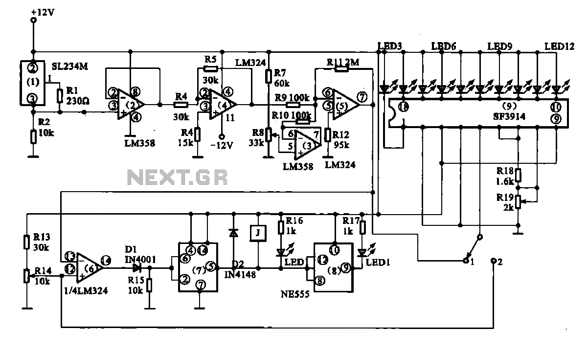
Vegetable greenhouse temperature detection control circuit. The greenhouse temperature detection control circuit is primarily composed of a temperature sensor SL234M, operational amplifiers LM324 and LM358, a dual time base circuit NE555, a relay, and a display driver circuit. The...
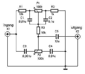
Here a simple design for an attractive tone. They operate on a passive principle, ie without amplification. The circuit only weakened and therefore require no power. As can be seen, the circuit is built with two T-filters in the...
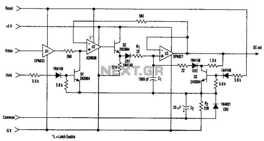
The amplitude of a video signal can be measured using a straightforward circuit that functions as a modified standard peak detector. This device is capable of verifying RGB signals produced by video RAMDACs. U1 is a high-speed buffer, while...
Cook in advance to open the door with a coal stove; before using the fire, it should be strong. This is an automatic door opening device that can automatically open the door before the regular homeowner, eliminating the need...
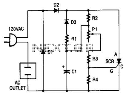
This circuit allows any standard household bulb to shimmer or blink. It is compatible with incandescent lights up to 200 W and operates on standard 120 Vac. The circuit employs a silicon-controlled rectifier (SCR) to create the shimmering effect....
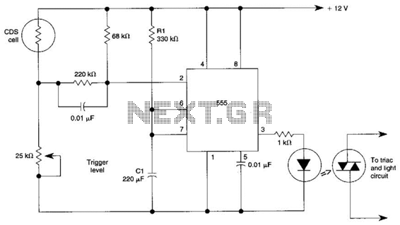
This circuit can control the on/off cycle of a light using a CDS photocell and turn it off after a preset period. The light can only be activated when the CDS cell is in darkness, and it remains on...
Warning: include(partials/cookie-banner.php): Failed to open stream: Permission denied in /var/www/html/nextgr/view-circuit.php on line 713
Warning: include(): Failed opening 'partials/cookie-banner.php' for inclusion (include_path='.:/usr/share/php') in /var/www/html/nextgr/view-circuit.php on line 713