
Coal stove door automatic door remote control circuit
The automatic door opening device described employs a monostable multivibrator circuit configuration, which is characterized by its ability to maintain a stable output state until triggered by an external signal. The use of transistors VT2 and VT3 in this configuration allows for a quick response to input signals, making the device suitable for environments where timely door access is essential. The inclusion of a microphone as an input sensor enhances the functionality, enabling the device to respond to auditory stimuli, thus providing a hands-free operation. The timing aspect, controlled by the alarm clock, ensures that the door can be opened at predetermined intervals, adding a layer of automation that can be beneficial in various applications, such as in homes or commercial settings where coal stoves are utilized.
The simplicity of the circuit design, combined with its effective operation, makes it accessible for users with varying levels of technical expertise. The ability to integrate this device with existing coal stove setups allows for greater convenience and efficiency, reducing the reliance on manual intervention for door operation. Overall, this automatic door opening device represents a practical solution for enhancing accessibility and improving the user experience in environments where coal stoves are in use.Cook in advance to open the door with a coal stove, before using the fire to be strong. Here's an automatic door opening device, it can automatically open the door before the regular home owner, eliminating the need for employers to fire doors and other fire exuberant time. The device structure is simple, easy selection, for the majority of users to burn briquette stove imitation.
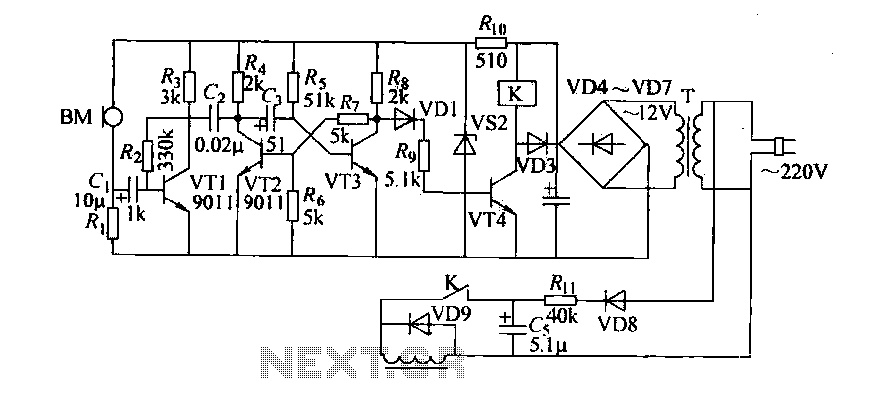
18-42 is a circuit diagram stove automatically open circuit principle coil device. It is actually a voice circuit, coal stove. Timing open, use the alarm clock to control. The main part of the circuit is a monostable circuit VT3 VT2 constituted. Monostable circuit works is: after turning on the power, the power provided to the anode through a resistor Rs VT3 large enough base bias, like it is in saturated conduction state, the collector potential root low around 0. 2V about. While the collector potential VT3 through wind resistance and R, the partial pressure, the transistor provides a lower base potential vrz, it is in the OFF state.
If the vote is activated external signal, this state (VT2i off, VT3 saturation) can be kept down, so called steady state. At steady state, the collector potential of the high VT2, VT3 base potential is low, and the capacitance of the collector VT2 G- termination, VT3 other end of the base, so there is a certain charge voltage G, electrode left and right is the positive or negative.
When the wire VT2 collector and emitter instantaneous short circuit, VT2 set electrode potential by the sudden decrease, but the voltage of the capacitor G is not about the mutation, so VT3 base potential should be reduced, so that the VT3 is turned OFF . After VT3 end, the collector potential of the horse rises high, because the base potential VT2 VT3 is determined by the collector potential via a resistor Rs, flat partial pressure is obtained, so also with the electric potential base VT2 significantly increased, so the VT2 cut into saturation.
Over time, the G charge charged through R5 and VTZ the e : c pole gradually bleed, the right end of the potential that is VT3 base potential coriander gradually increased, when raised to o. At around 6V, VT3 will begin conducting, the collector electric , digits begin to decrease, the wind, the partial pressure of goods, VT2 base potential to begin to reduce, VTZ began to withdraw from saturation, its collector potential began to rise, coupling G small-minded, and base potential VT3 further increases, VT3 further guide escape, leading to its saturation, leaving VT2 deadline, which will be restored to its original stable state.
Visible, monostable circuit triggered by external signal (such as the use of wire momentary shorts VT2 c, after e :) poles can flip quickly from the steady state into another temporary state until after a period of delay, the fork re-turn back to the original steady state. The alarm clock is picked up by the microphone BM. Usually the impedance presented by the microphone is relatively large, the collector potential of VT1 high, the monostable circuit is in a steady-state condition.
At this low collector potential VT3. VT4 is off, the relay does not pull. When the microphone being subjected to strong tones, the internal impedance dramatically smaller, this change makes C. The rapid increase in the potential of the left, the equivalent of the base of the transistor VT1 enter a positive pulse, so that the base potential of VTI's rapid rise, its collector potential decline rapidly.
This change in voltage via a capacitor c2 transmitted VT2 collector, the collector potential VT2 has declined rapidly (the equivalent of VT2 c pole e very short answer it). So the one-shot circuit to generate inverted changes described above, the circuit immediately turn people temporary steady state, this time, a sudden rise in the collector potential VT3, VT4 causing saturation.
So relay operation occurs, K Pull, the solenoid is energized to generate the operation, touched organ set on the door, so that in the spring to pull the door open under the force.
Related Circuits
This wikibook serves as an introductory text about electric circuits, covering the fundamentals of electric circuit theory, circuit analysis, and circuit design. It is intended as a companion reference for first-year Electrical Engineering undergraduates. Topics include AC and DC...
The SE555/NE555 timer was first introduced by the Signetics Corporation around 1971. Pin connections and functions are as follows: Pin 1 (Ground) - This pin serves as the ground or common pin, representing the most negative supply potential of...
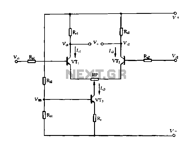
A differential amplifier with a constant current source is illustrated in Figure 1-27. As long as capacitor C3 is maintained at a constant value, capacitors C1 and C2 cannot be simultaneously increased or decreased, preventing voltage drift. The differential...
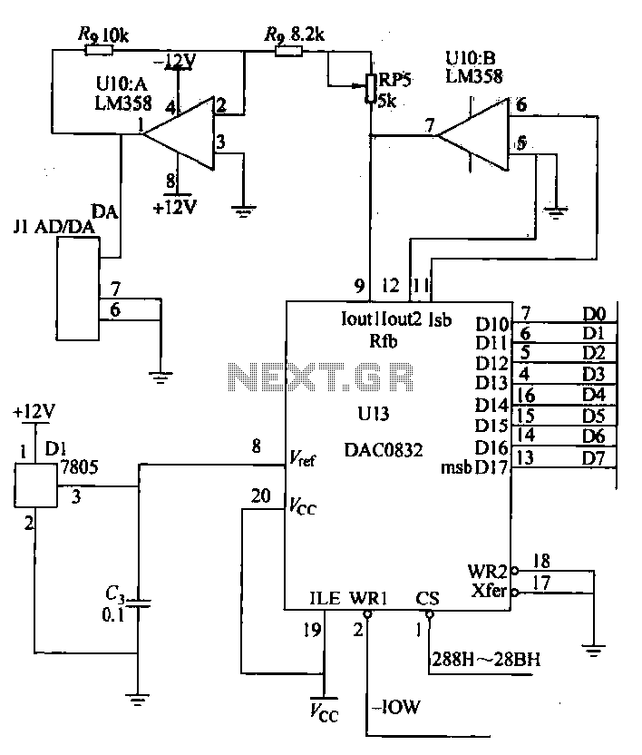
A digital-to-analog (D/A) conversion circuit utilizing the DAC0832 and the operational amplifier LM358, featuring two output channels with unipolar voltage output. The digital input range is from 00H to FFH, which corresponds to an output voltage range of 0V...
This circuit serves as a decorative element or indicator, featuring adjustable flashing or dancing speeds of LEDs and the ability to create various light patterns. It comprises two astable multivibrators; the first is constructed using transistors T1 and T2,...

This series-feedback configuration of components provides a high input impedance and stable, wide-band gain video amplifier suitable for general-purpose applications. Below is the schematic representation of the circuit. The described video amplifier circuit employs a series-feedback topology, which is instrumental...
Warning: include(partials/cookie-banner.php): Failed to open stream: Permission denied in /var/www/html/nextgr/view-circuit.php on line 713
Warning: include(): Failed opening 'partials/cookie-banner.php' for inclusion (include_path='.:/usr/share/php') in /var/www/html/nextgr/view-circuit.php on line 713