
temperature sensor circuit
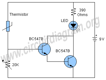
The temperature sensor circuit utilizes a thermistor, which is a critical component that responds to temperature changes by altering its resistance. This property allows it to function effectively in detecting thermal variations. The BC547B transistors, arranged in a Darlington configuration, provide a significant amplification of the current, thereby increasing the circuit's sensitivity to small changes in temperature. The Darlington pair is particularly advantageous in applications where a higher gain is required, enabling the circuit to respond to subtle temperature shifts.
The LED serves as a visual indicator, illuminating when the circuit detects a sufficient increase in temperature. The current-limiting resistor is essential to prevent excess current from damaging the LED, ensuring longevity and reliable operation. The inclusion of a 20K variable resistor allows for fine-tuning of the circuit's response, enabling the user to set the desired activation temperature for the LED.
In summary, this simple temperature sensor circuit is an effective solution for heat detection, leveraging the properties of a thermistor and the amplification capabilities of a Darlington pair to provide a reliable output in the form of an illuminated LED. The design is user-friendly and can be easily assembled with minimal components, making it suitable for various applications in temperature monitoring and alarm systems.The schematic shown here is a project of a simple temperature sensor circuit or we can also say it a heat sensor circuit, which will activate an LED when receive heat. The circuit is easy to make and using only few components. The two BC547B transistors are connected as a darlington pair to increase the sensitivity of the circuit.
Other components of the circuit are an LED, a current limiting resistor for LED, a 20K variable resistor and a thermistor. A thermistor is a device that limits the passing of current through it according to the temperature. In the condition of low temperature they have higher resistance and in the opposite condition when they receive heat their resistance starts decreasing rapidly and current starts to flow.
Working of the circuit is simple when the thermistor will receive heat its resistance will decrease due to which the transistors will become switched on and the voltage will starts passing through the transistors which will activate the LED. The 20K resistor is used to adjust the circuit to activate the LED on the required heat or temperature.
🔗 External reference
Related Circuits

The GH-75 type circuit is a hydrogen atom welder that utilizes hydrogen bonding without melting the workpiece. This process involves the use of a tungsten electrode to generate an electric arc, which effectively welds the workpiece in a hydrogen-protected...
This circuit represents a low-cost printer sharing device that was developed some time ago. The product was encapsulated in epoxy with a black dye and had a limited commercial release. The output impedance of this circuit is high, with...
A digital amplifier is a new device that IC manufacturers are eager to capitalize on, leading to the launch of unique digital amplifier products. Below are brief descriptions of some representative devices. The TA2022, produced by Tripath, is an...

An effort is being made to enhance the responsiveness of an electronic keyboard due to dissatisfaction with the current sensitivity to keystrokes. The initial step in this process involves measuring the speed of the fastest keystroke. To improve the responsiveness...
FIG. 284 illustrates a practical emergency power lighting system that activates automatically in the event of a sudden power outage. The fluorescent lights serve as emergency lighting. If the primary illumination lamp is turned off due to a power...

The LA4440 is a dual-channel audio power amplifier integrated circuit (IC) designed for stereo and bridge amplifier applications. In dual mode, it provides significant audio amplification for various audio systems. The LA4440 audio power amplifier is engineered to deliver high-quality...