
Simple FM Transmitter circuit schematic Long range short range using VMR6512 Hi-Fi Audio FM transmitter module
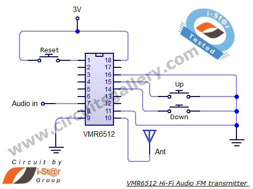
The VMR6512 FM transmitter circuit is designed for versatility in audio transmission applications. The integration of a DSP within the chip allows for complex audio processing, ensuring high fidelity in sound reproduction. The matching network facilitates impedance matching, which is critical for efficient RF transmission, minimizing signal loss and ensuring that the maximum amount of power is radiated by the antenna.
The reset functionality is essential for initializing the transmitter's operation, allowing it to start at a predetermined frequency and power level, which is crucial for maintaining consistent performance across various applications. The analog input pins are designed to accept audio signals directly from a pre-amplifier, making the design compact and efficient.
The digital audio input interface is particularly noteworthy as it supports multiple formats, providing flexibility in integration with various audio sources. The UP and DOWN control pins for frequency adjustment allow for real-time tuning of the transmitter, which is beneficial in dynamic operating environments where interference may occur.
For the antenna, the recommendation of a 1/4 wavelength design is based on its effectiveness in radiating RF energy efficiently and ensuring a good match with the transmitter's output. This design choice enhances the overall range and clarity of the transmitted audio signal, making the VMR6512 FM transmitter suitable for a wide range of applications from personal use to professional broadcasting.This article gives the FM transmitter circuit schematics with necessary explanation. The main component used here is the VMR6512 IC which is a highly integrated FM audio signal (Hi-Fi Audio FM) transmitter chip. You can use this as FM radio transmitter for different applications such as FM transmitter for car, digital FM transmitter, Hi-Fi wireles
s headphone, Conference Broadcasting System, accessories of audio-visual entertainment equipment and radio station in campus. This wireless audio transmitter chip integrates superior digital signal processor (DSP), matching network, frequency synthesizer and RF power amplifier.
So it can grasp FM audio modulation without any external components. You need a pre amplifier section in order to transmit our voice directly as FM. Refer my condenser mic pre amplifier circuit. Related article: Most simple FM transmitter circuit diagram Reset pin set to high PWL will reset the controller, DSP and frequency synthesizer. After reset, the communication frequency will be100. 0MHz and the power will be 115dBuV. The system begins working 160ms once the Reset signal becomes lower. Analog audio input Rin, Lin Rin and Lin is the analog audio input pin of VMR6512 module. There is a capacitor in the pin. So the other exterior components are not needed. Audio input impedance is approximately 56 k ©. Digital audio input interface consists of SCLK, DIN and FS. It can be set to I2S, DSP and Left Justified three different formats through commanding and connected without a glitch with almost all the DSP.
UP and DOWN pins are used to modify the operating frequency exclusive of the external controller. Each low PWL impulse larger than 0. 05 seconds of UP / DOWN pin will make output RF power raise or decrease 0. 1MHz. If you stay low PWL, then the operating frequency will change continuously every 0. 3 seconds. As the unit has internal matching networks, RF output signal pin should be directly connected to the line without any components. It is proposed that antenna should use 1/4 wavelength wire or rod antenna. 🔗 External reference
Related Circuits
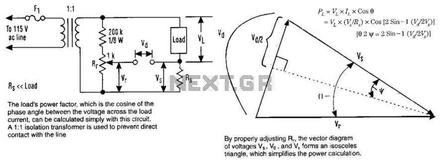
The load's power factor, defined as the cosine of the phase angle between the voltage across the load and the load current, can be calculated using this circuit. An isolation transformer with a 1:1 ratio is employed to prevent...
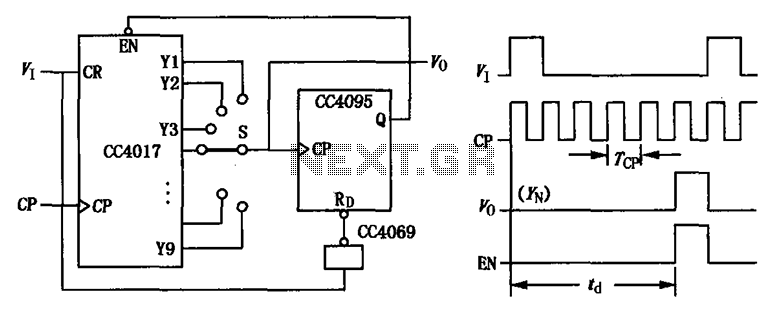
CC4017 counter/distributor featuring a circuit diagram of the delay. The CC4017 is a decade counter and distributor that counts from 0 to 10, providing ten output states. It is commonly used in various digital applications for counting purposes, such as...
A radio remote control system utilizing DTMF (Dual-Tone Multi-Frequency) technology is presented. This circuit allows for the control of various electrical appliances through radio frequency signals. The described radio remote control system employs DTMF tones, which are generated by a...

This project involved the design of an audio amplifier that delivers substantial output power while maintaining a minimal parts count and high quality. The power amplifier section utilizes only three transistors along with a few resistors and capacitors arranged...
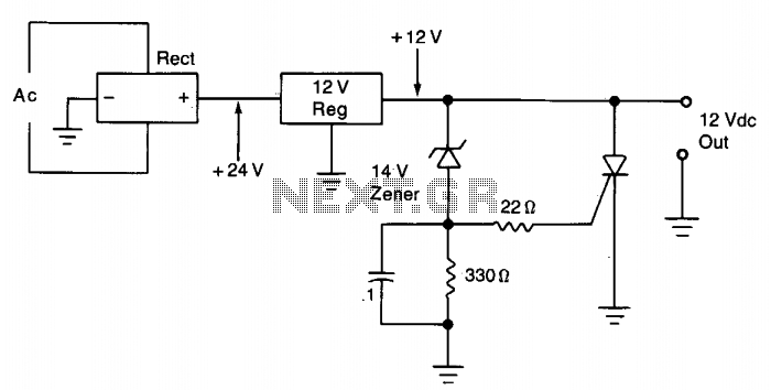
The silicon controlled rectifier (SCR) is designed to handle at least the current provided by the power supply. It is connected in parallel across the 12 V DC output lines but remains inactive until a voltage is applied to...
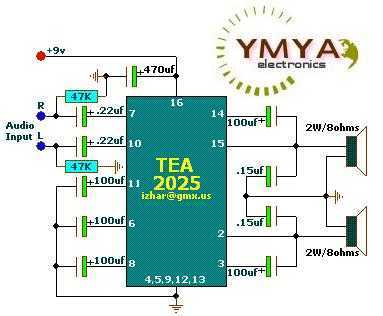
These circuits are based on TEA2025, a monolithic integrated audio amplifier in a 16-pin plastic dual in-line package manufactured by UTC. The circuit includes an internal thermal protector and is designed for portable cassette players and radios. It can...