
Humidity Tester Circuit Using Sensor
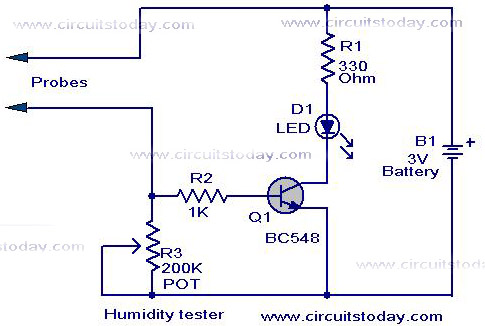
The humidity tester circuit is designed to provide a visual indication of humidity levels using basic electronic components. The core components include a light-emitting diode (LED), a transistor, and several resistors, which together form a straightforward yet effective humidity sensing mechanism.
In this circuit, the LED serves as an output indicator, illuminating when humidity levels exceed a predetermined threshold. The transistor functions as a switch, controlling the LED based on the input signal derived from a humidity-sensitive element, such as a hygrometer or a humidity sensor. The resistors are used to set appropriate biasing levels for the transistor and to limit the current flowing through the LED to prevent damage.
The schematic layout typically depicts the humidity sensor connected to the base of the transistor. When the sensor detects increased humidity, it generates a voltage signal that turns the transistor on, allowing current to flow from the collector to the emitter. This action activates the LED, providing a visual cue of the humidity status. Resistors in the circuit assist in stabilizing the transistor's operation and ensuring that the LED operates within safe limits.
The simplicity of this circuit makes it suitable for educational purposes, as well as for practical applications in environments where humidity monitoring is essential, such as greenhouses, storage facilities, or laboratories. The design can be easily modified or expanded to include additional features, such as an adjustable threshold or an audible alarm, by incorporating more components while maintaining the fundamental principles of operation.A simple humidity tester circuit using just a LED, transistor, and a few resistors is explaind with a neat circuit schematic.. 🔗 External reference
Related Circuits
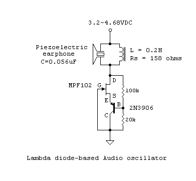
The usual procedure for producing sustained oscillations in tuned L-C networks involves overcoming circuit losses through designed-in positive feedback or regeneration. During the circuit's on-transient, oscillations build up, triggered by the thermal noise of circuit elements. Two possible situations...

This optodetector measures the position of the ball by the amount of light transmitted by the infrared LED. It generates a linear signal across the small area of the detector, rather than simply providing an "on" or "off" output....
This design utilizes four integrated circuits (ICs) and features four input circuits with four independent outputs, along with a single master reset switch. The outputs are configured with light-emitting diodes (LEDs), which can be modified to control lamps or...
Following last year's rediscovery of radio-controlled flight, there is a growing interest in the hacking and modification potential of the budget-friendly 9-channel FlySky FS-TH9X transmitter (also marketed as Turnigy/Eurgle, etc.). The original 2.4GHz RF module and firmware are quite...
This circuit utilizes a sawtooth oscillator along with an output amplifier that drives a transistor. The components C1, C2, and L1 are essential for the oscillator's operation, forming a tank circuit that must be tuned to the resonant frequency....

This is a simple use of the PIC 16F84 about a diode tester. Test procedure: We set "1" to PB0 and "0" to PB3. If the diode is ok and opens, then at PA0 we have "1". If PA0...