
Humming and Transmission issues
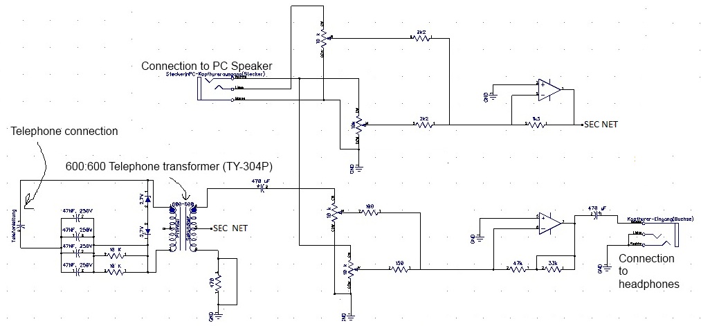
Operational amplifiers (op-amps) are widely used in various electronic circuits for signal amplification, filtering, and other applications. Humming issues in op-amp circuits often arise from power supply noise, ground loops, or improper circuit layout. This noise can manifest as an audible hum in audio applications or as unwanted noise in signal processing tasks.
To address humming issues, it is essential to ensure that the power supply used for the op-amp is adequately filtered and regulated. Utilizing decoupling capacitors close to the power supply pins of the op-amp can help mitigate high-frequency noise. Additionally, ensuring that the ground connections are properly designed to avoid ground loops is crucial. A star grounding technique can be employed, where all ground connections converge at a single point, minimizing the potential for interference.
Transmission issues may occur due to impedance mismatches, signal degradation over long distances, or inadequate shielding. To combat these issues, it is advisable to use appropriate transmission line techniques and ensure that the circuit impedance matches the source and load impedances. Employing twisted pair cables or coaxial cables can also help reduce electromagnetic interference (EMI), thereby improving signal integrity.
In summary, addressing humming and transmission issues in op-amp circuits requires careful consideration of power supply integrity, grounding techniques, and transmission line characteristics to ensure optimal performance in electrical engineering applications.Hello. You seem like people who know their stuff. I`d appreciate you looking at op amp - Humming and Transmission issues - Electrical Engineering and.. 🔗 External reference
Related Circuits
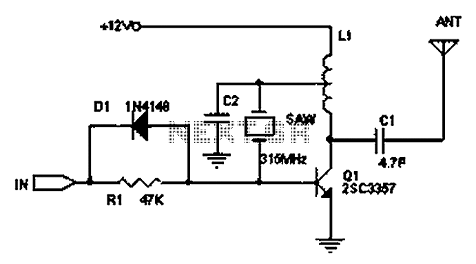
The circuit principle involves the use of an LC oscillator, which typically experiences significant frequency drift. Surface Acoustic Wave (SAW) devices have emerged as a solution to this issue, offering frequency stability comparable to that of crystal oscillators. SAW...
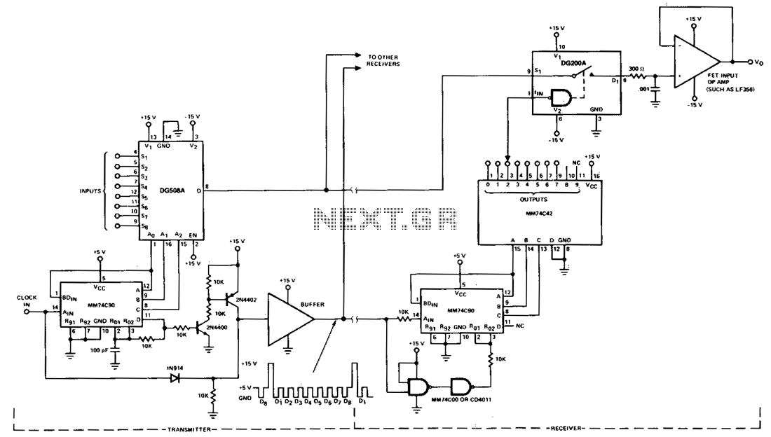
This circuit illustrates a typical multiplex system designed to transmit one of eight inputs to a remote location. A 5-V pulse train is transmitted through a separate channel to execute timing and synchronization functions. A 15-V reset pulse is...
The AN7158N is an integrated circuit designed for a power amplifier with an output of 7.5W (16V, 4Ω) that features low noise and low distortion. It is suitable for use in television sets with multi-sound capabilities. The design incorporates...
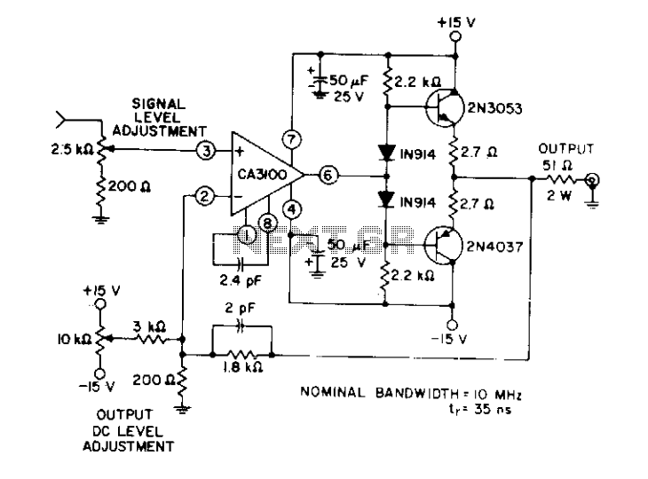
This circuit utilizes a wideband, high slew rate CA3100 BiMOS operational amplifier. The slew rate for this amplifier is 28 V/µs. The output swing is 9 volts peak-to-peak into a terminated line, measured at the termination. The CA3100 BiMOS operational...
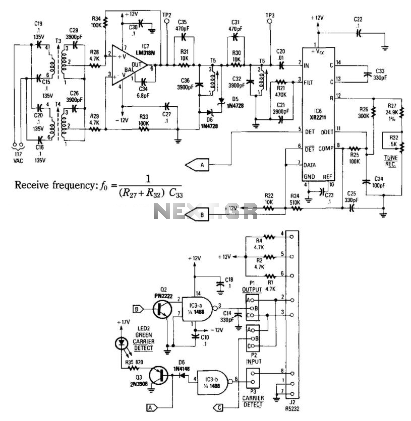
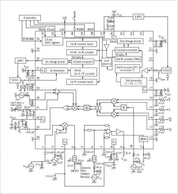
This receiver consists of an input network, amplifier IC7, FSK PLL detector IC8, and output amplifier/interface circuits Q2, Q3, IC3A, and IC3B, which include a 1488 Quad RS232 line driver for the carrier-current signal. The tuned amplifier IC7 amplifies...
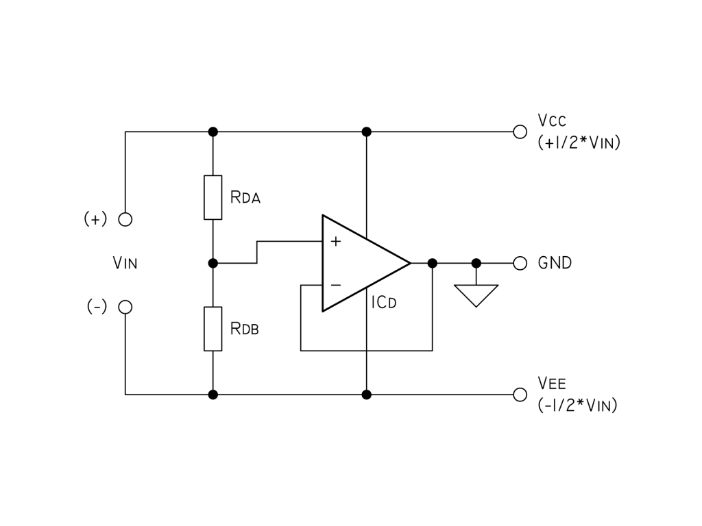
To eliminate noise, a 100µF capacitor and a 100nF bypass capacitor are used across the supply, along with two 10nF capacitors in parallel with the resistors Rda and Rdb (each 10K). For current limiting, a 22K resistor is paralleled...