
Based on Bluetooth wireless transmission-reception circuit design schematics
The circuit utilizes a SAW device to enhance frequency stability, making it suitable for applications where precise frequency control is essential. The simplicity of the circuit design, compared to traditional crystal oscillators, allows for easier implementation and integration into various systems. The transmitter circuit can be configured to operate at high frequencies, leveraging the capabilities of SAW technology to maintain consistent performance over a range of environmental conditions.
In practical applications, the transmitter can be paired with a super-regenerative receiver, which is advantageous due to its low power requirements and cost-effectiveness. The super-regenerative receiver operates by exploiting the oscillation characteristics of the circuit, which can be fine-tuned for sensitivity based on the specific requirements of the application. Despite its benefits, users must be aware of the trade-offs associated with the super-regenerative design, particularly in terms of selectivity and susceptibility to interference.
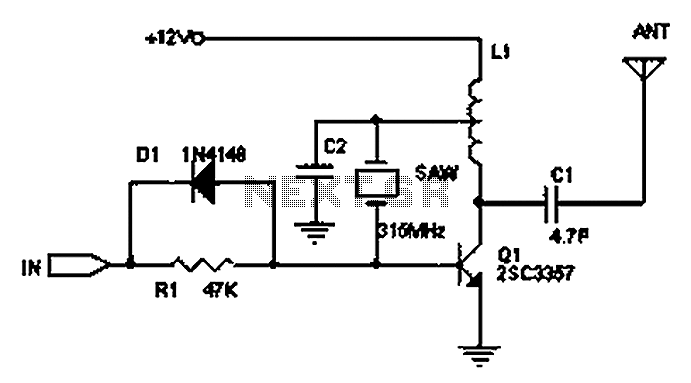
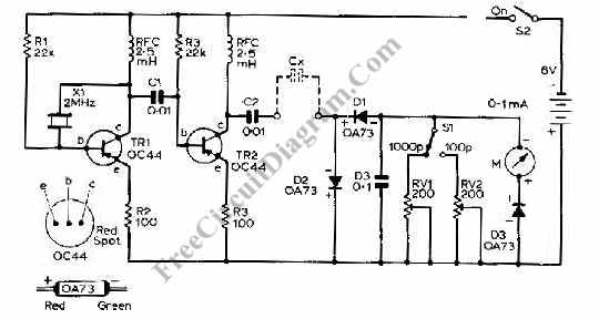
For enhanced performance, it may be beneficial to incorporate additional filtering stages or to employ a superheterodyne receiver configuration, which can provide improved stability and selectivity at the expense of increased complexity and cost. This configuration allows for better handling of interference and more precise frequency selection, making it suitable for applications requiring high fidelity and reliability in signal reception. Overall, the integration of SAW devices in this circuit design represents a significant advancement in achieving stable, high-frequency transmission and reception capabilities in electronic communication systems. Circuit Principle: Using LC oscillator frequency drift is more serious. SAW devices appear to solve this problem, the frequency stability of the crystal substantially the same, and its fundamental frequency of up to hundreds of megabytes or even gigahertz. Without octave, compared with the crystal oscillator circuit is extremely simple. The following circuit is a common transmitter circuit, due to the use of SAW devices, the circuit is very stable, even grasping antenna, acoustic or other parts of the circuit, the transmission frequency will not drift. Up to 200 meters, while a super-regenerative receiver may use a circuit or superheterodyne circuit, the super-regenerative circuit low cost, low power consumption of up to 100uA, good super regenerative circuit to adjust the sensitivity level and high level, the oscillation level, placed in a mixer and two similar superheterodyne receiver.
However, job stability super regenerative circuit is relatively poor, poor selectivity, thereby reducing interference.
Related Circuits
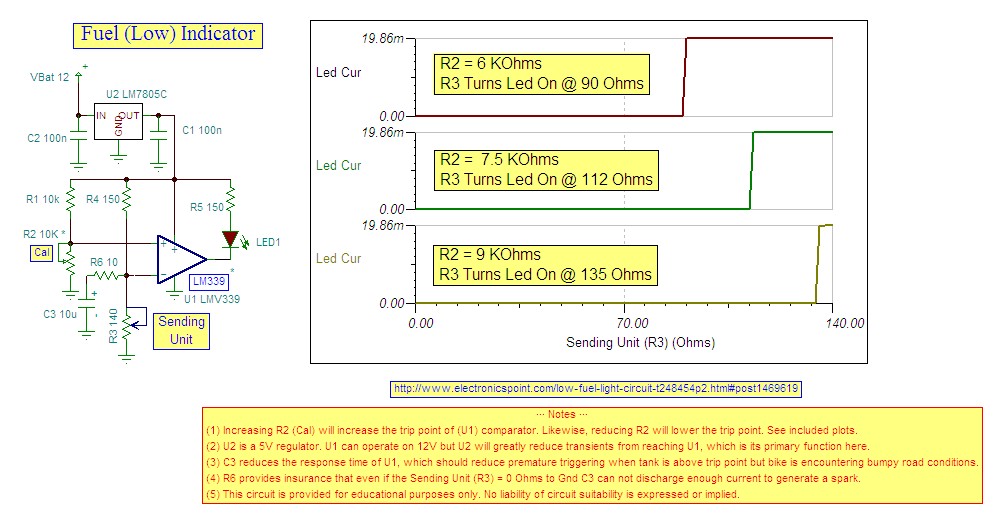
Research indicates that the sender will register a resistance of 100 ohms when the fuel tank is empty, making a trigger reading of 80 ohms optimal. The fuel gauge sender is a critical component in monitoring the fuel level within...
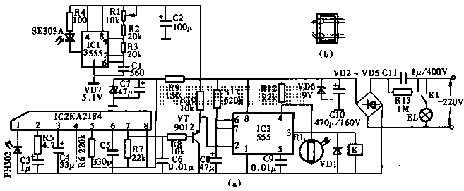
This circuit utilizes the KA2184 infrared receiver ASIC for an infrared remote control dimmer light application, as depicted in the schematic. The infrared signal is generated by a pulse generator using an NE555 timer integrated circuit. The NE555 produces...
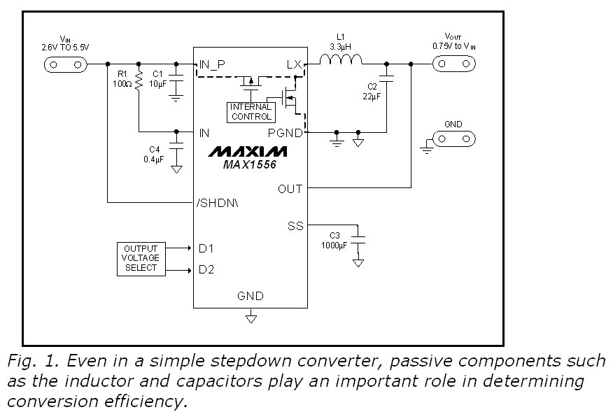
This blog provides insights into SMPS (Switched-Mode Power Supply) circuit diagrams. It offers valuable information for those interested in understanding this topic. Switched-Mode Power Supplies (SMPS) are crucial in modern electronic devices due to their efficiency and compact design. An...
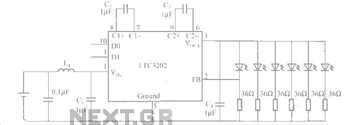
The LTC3202 is a device from Linear Technology that eliminates the need for a charge pump gated oscillator. It is designed as a charge pump for driving white LEDs powered by a lithium-ion battery. To address noise issues, the...
This capacitance meter circuit is similar to previous meter circuits, but it utilizes transistors instead of logic gates. A schematic diagram is provided. The capacitance meter circuit operates by measuring the capacitance of a capacitor through a time-based method. The...

This alarm is designed to activate its siren only once. When the alarm is triggered, the siren will sound for a predetermined duration before automatically turning off and remaining inactive. The alarm system features a single zone with independently...