
Issues with the OPA548 current limiting
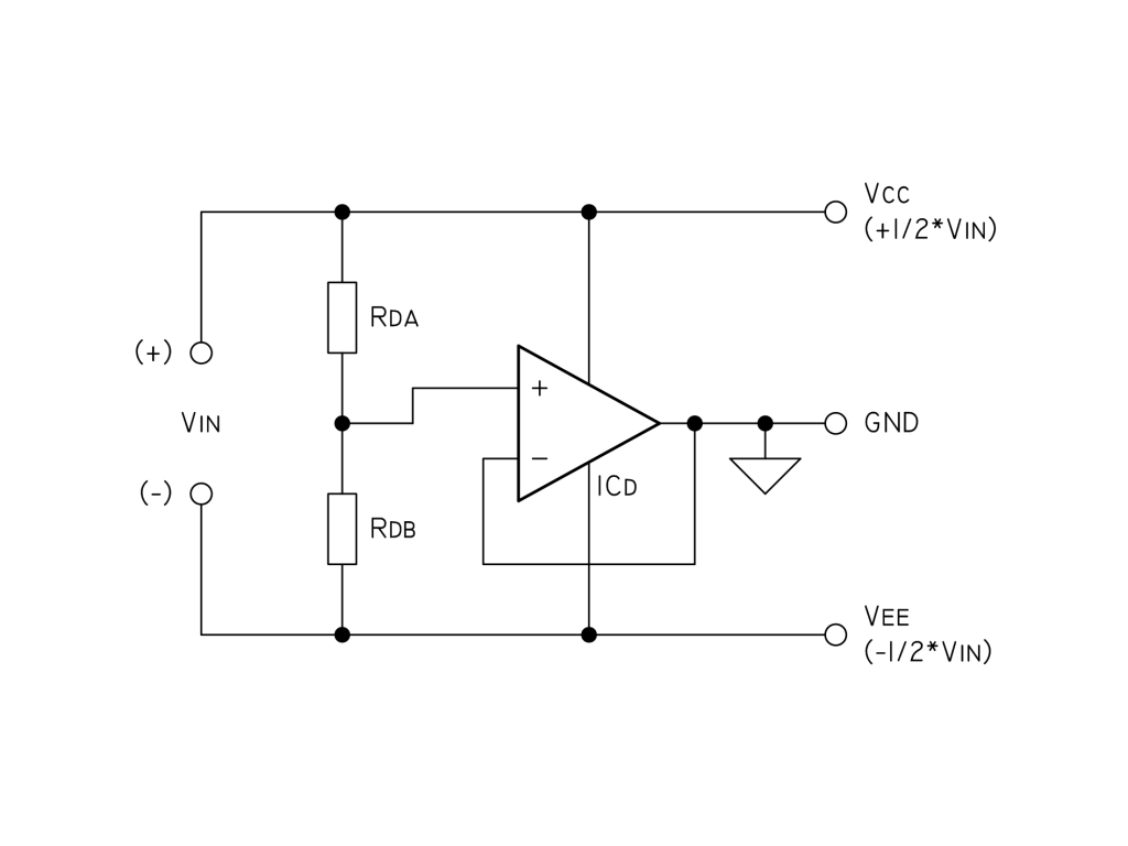
The circuit described involves the OPA548 operational amplifier, which is utilized in a configuration aimed at minimizing noise and ensuring stable operation under varying load conditions. The capacitors employed serve dual purposes: the larger electrolytic capacitor (100µF) provides bulk decoupling, while the smaller capacitors (100nF and 10nF) act as high-frequency bypass capacitors to filter out noise from the power supply lines. The resistors Rda and Rdb, each valued at 10K, are likely part of a feedback or gain setting arrangement that influences the overall performance of the amplifier.
The current limiting mechanism is established through a combination of a 22K resistor and a 10nF capacitor connected to the Ilim pin. This configuration is intended to set a threshold for current sinking operations. The connection of pin 7 (E/S) to V+ indicates that the amplifier is configured for normal operation, allowing for current sourcing and sinking based on the load conditions.
The inclusion of free-wheeling diodes across the output is critical in protecting the circuit from back EMF generated by inductive loads, ensuring safe operation during transient conditions. The Zobel network, consisting of a 4.7Ω resistor and a 100nF capacitor, is employed to stabilize the amplifier by damping high-frequency oscillations that could lead to instability, particularly when capacitive loads are present.
The varying current limiting behavior observed when sinking versus sourcing may indicate issues with the common-mode input range of the OPA548. The operational amplifier is designed to function within specific voltage limits, and exceeding these can lead to unexpected behavior. It is essential to maintain the input signals within the specified common-mode range to ensure proper operation.
Further investigation into the high-frequency response of the circuit is warranted, particularly by utilizing an oscilloscope to observe the GND output for any oscillations that could be influencing the performance. The recommendation to verify the integrity of the power supply and ensure it is floating without unintended ground paths is crucial, as any parallel paths could introduce noise and instability.
Overall, the described circuit is a complex arrangement that requires careful consideration of component values, layout, and external influences to achieve the desired operational characteristics. Adjustments to gain settings and feedback configurations may help mitigate the observed issues, improving the amplifier's performance under varying load conditions.In order to eliminate noise, I`ve used a 100uF capacitor and a 100nF bypass capacitor across the supply and two 10nF capacitors in parallel with the resistors Rda and Rdb (those are 10K each), As for the current limiting, I`ve used a 22K resistor paralleled with a 10nF capacitor, from pin 3 (Ilim) to V-. I`ve tied pin 7 (E/S) to V+. I`ve used two free-wheeling diodes across the output and, of course, a zobel consisting of one 4, 7R resistor and a 100nF capacitor. The problem is that the OPA548 limits the current to around 700-800mA when sinking (output shorted to V+), and that current pretty much depends on the supply voltage.
However, when sourcing (output shorted to V-), it behaves as expected, since the current is limited to 2A (Rlim = 22k). Why does the current limit doesn`t work properly when sinking Is it a defective design A damaged chip Or is it that the current limiting is only applied when the OPA548 is sourcing I`ve tried everything!
I`ve changed the resistor values, taken out the zobel and the diodes, untied the E/S pin from V+, and the behaviour is still the same! What is wrong Have you looked at the "GND" output with a scope to see if there is a high frequency (>100KHz) oscillation This could be a small 100MHz squeak of a few hundred mV, or a several Vpp oscillation.
Note that "floating" your scope by breaking the ground pin is cheating. You are still adding extra capacitance to the "GND" point through the AC line and may actually "snub" the oscillation. Ideally the scope should be "grounded" to one of the rails and the GND node probed. Use a battery powered, truly "floating" scope if possible. You can also use a AC voltmeter between one of the rails and "Ground" to check for any AC voltages. Any AC voltage more than a few mV across the rails may mean an oscillation. Most hand-held DMM`s can detect AC up to a few MHz. Do you have supply bypass capacitors on the load side (between "GND" and VCC or VEE) This is a direct capacitive load on the output - which op-amps do NOT like.
Even with a Zobel "snubber" - any bypass caps on the load side are "bypassing" the snubber. Low ESR ceramic caps directly on the output can really make an amp scream. One thing you can try is placing the OPA548 in an AC noise gain of 5-10. To do this; Set a non-inverting "AC gain" of, say 10. Add the feedback resistors R1 (1K) and R2 (9K) as shown in Figure 1, but tie R1 to the non-inverting input (Rd tap) through a 22uf cap. This will still give you a DC gain of one referred to the non-inverting input (though the output may be slightly noisier due to the AC gain).
Are you sure the source supply is truly "floating" Could there be a parallel "path" to ground through a test instrument or other circuit component Is there more current being drawn while at mid-supply than you expect This may help cure a number of possible ills. It raises the noise gain to avoid oscillations (including with capacitive load as we discussed in your previous thread).
When you short to positive supply, it pulls the inverting input outside its common-mode range. This circuit should avoid that. I think the short condition may also turn on differential clamps on the input. This may help with that situation, too. I`ve had no time to check this out in detail and I travel tomorrow. Give this a try. My power supply is linear regulated. I have no capacitive loads, and I even taken out the zobel. Indeed I saw a small ripple (273mVpp) when shorting directly the output to V+. That ripple would appear on the positive input as well, with a much smaller magnitude (5mVpp). Last night I`ve tested this with some resistive loads, and I could sink currents up to the limit of 2A without a problem. A direct short without using the ammeter would give a short circuit measuring 1. 05A (read on the power supply display). This suggests that it is really an issue related with the common mode. But since I only need to guarantee 2A w 🔗 External reference
Related Circuits
This is a INA159 Dual-Polarity, Bidirectional Current-Shunt-Monitor Circuit. This circuit uses OPA340 because it has near rail-to-rail input and output swing. The INA159 is an integrated circuit designed for high precision current sensing applications. It is capable of measuring bidirectional...
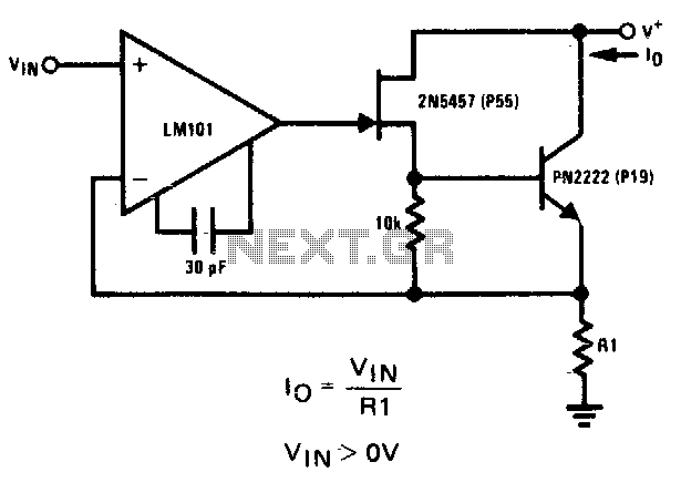
The 2N5457 JFET and PN2222 bipolar transistor exhibit high output impedance. Employing Rl as a current sensing resistor to feedback into the LM101 operational amplifier yields significant loop gain for negative feedback, thereby improving the circuit's capability as a...
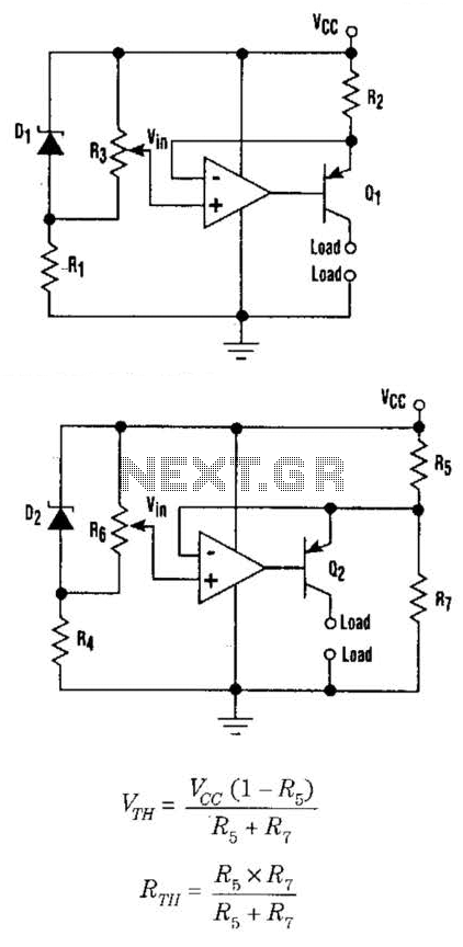
This setup can function as a cost-effective current source with an output accuracy of 1%. However, the voltage offset can activate the current source even when Vqq equals Vin. Modifying the configuration of Figure 1 can resolve the issue...
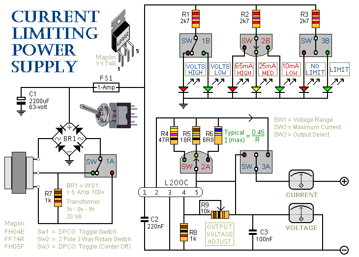
SW3 is the on/off switch. It also lets you choose between the output with the current limit and the one without. SW2 provides a selection of three different limits. You can increase or decrease this number if you wish....
An inquiry regarding operational amplifier (op-amp) humming and transmission issues in the context of electrical engineering. Operational amplifiers (op-amps) are widely used in various electronic circuits for signal amplification, filtering, and other applications. Humming issues in op-amp circuits often arise...
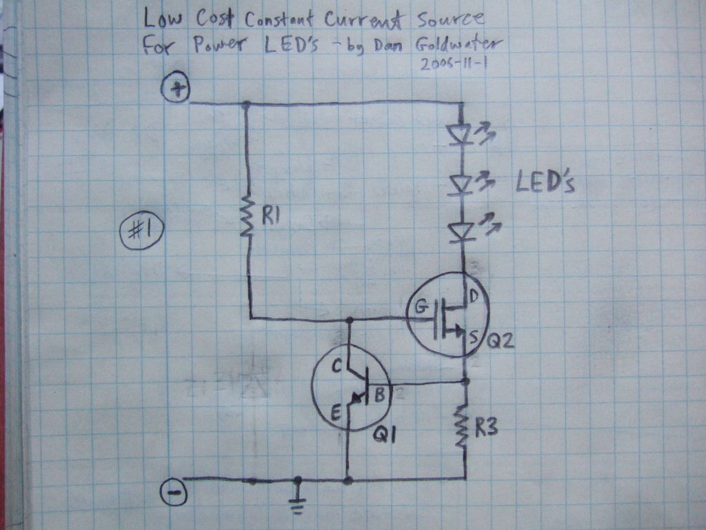
Here is a simple and inexpensive ($1) LED driver circuit. The circuit functions as a constant current source, ensuring that the LED maintains consistent brightness. The LED driver circuit is designed to provide a stable current to the LED, which...