
Hv Power Supply With 9 To 15Vdc Input Circuit

The Hartley oscillator is a type of LC oscillator that utilizes a tank circuit composed of an inductor and a capacitor to produce oscillations. In this configuration, the oscillator generates an alternating current (AC) signal at a specific frequency determined by the values of the inductors and capacitors in the circuit. The output of the Hartley oscillator is then fed into a step-up transformer, which increases the voltage level of the AC signal.
The step-up transformer operates on the principle of electromagnetic induction, where the primary winding receives the input voltage from the oscillator, and the secondary winding produces a higher voltage output. The turns ratio of the transformer determines the extent of the voltage increase. For example, if the primary winding has 10 turns and the secondary has 100 turns, the voltage is stepped up by a factor of 10.
When the output voltage from the transformer is further processed by an additional circuit, referred to as circuit B, it can enhance the negative high voltage generated. This additional circuit may include components such as diodes for rectification, capacitors for smoothing, and additional inductors for further voltage multiplication. The combination of the Hartley oscillator and the transformer, along with the voltage multiplication circuit, can produce a significant negative high voltage output, suitable for applications requiring high voltage levels, such as in certain types of electronic ignition systems or high-voltage power supplies.
Overall, the design and implementation of this integrated circuit require careful consideration of component ratings, circuit layout, and safety precautions due to the high voltages involved. Proper insulation and protective measures must be employed to prevent electrical hazards during operation. The combination Hartley oscillator/step-up transformer shown in A can generate significant negative high voltage, especially if the voltage output of the transformer is multiplied by the circuit in B.
Related Circuits
This chapter presents a variety of circuits for basic power supplies, including both line-powered and inverter types, some of which feature regulators, modulation inputs, and additional functionalities. Several circuits have been reverse-engineered from actual commercial products, and others, designed...
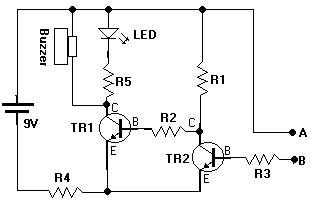
This document presents a water sensor circuit designed to monitor soil moisture levels for plants. This circuit is straightforward and is constructed using five resistors, two transistors, an LED, a buzzer, and a battery. The operation of the circuit...
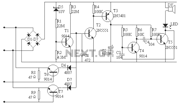
The phone alarm device is designed to monitor and prevent unauthorized use of a telephone line. When interference signals are detected on the line due to theft attempts, the alarm activates, preventing the thief from making calls while alerting...
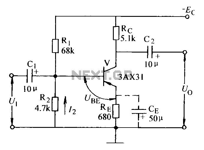
Current negative feedback voltage divider biased circuit diagram. The current negative feedback voltage divider biased circuit is a configuration commonly used in electronic amplifiers to stabilize the operating point and improve linearity. This circuit typically consists of an amplifier, a...
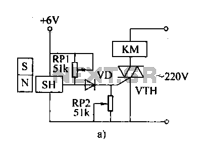
The automatic weapon features a magnetic switch circuit that is simple, reliable, has a low failure rate, and offers good versatility. It can be used for output performance or converted into mechanical displacement applications. The circuit diagram utilizes a...

CB85-10 leakage protection circuit diagram, T for the trip coil, SB is the test button, Ri is simulated human resistance. The CB85-10 leakage protection circuit is designed to enhance safety by detecting leakage currents and disconnecting the electrical supply to...